Tripp Lite BP-260 Bedienungsanleitung
Tripp Lite
Nicht kategorisiert
BP-260
Lies die bedienungsanleitung für Tripp Lite BP-260 (12 Seiten) kostenlos online; sie gehört zur Kategorie Nicht kategorisiert. Dieses Handbuch wurde von 3 Personen als hilfreich bewertet und erhielt im Schnitt 4.2 Sterne aus 2 Bewertungen. Hast du eine Frage zu Tripp Lite BP-260 oder möchtest du andere Nutzer dieses Produkts befragen? Stelle eine Frage
Seite 1/12
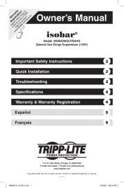
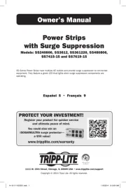
Owner’s Manual
External Battery Enclosure
for 12V/24V Inverter/Charger
Systems
Model: BP-260
Español 5 • Français 9
PROTECT YOUR INVESTMENT!
Register your product for quicker service
and ultimate peace of mind.
You could also win an
ISOBAR6ULTRA surge protector—
a $100 value!
www.tripplite.com/warranty
1111 W. 35th Street, Chicago, IL 60609 USA • www.tripplite.com/support
Copyright © 2017 Tripp Lite. All rights reserved.
17-10-206-930750.indb 1 10/31/2017 1:13:23 PM

2
Introduction
Package Includes
Important Safety Warnings
When used with the 98-121 batteries (available separately from Tripp Lite), the BP-260
External Battery Enclosure provides extended runtime capability for 12V or 24V Inverter/
Charger Systems. Multiple BP-260 enclosures can be daisy-chained to further increase
runtime. The BP-260 battery enclosure accepts up to two 98-121 battery modules.
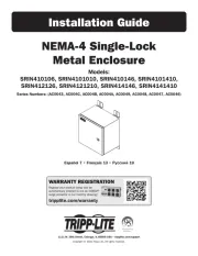
(1) Heavy-duty Steel Enclosure
(4) 1/4-20 x 3/4” Hex Head Nuts and Bolts
(1) 30” #6 Gauge Red Cable with Ring Tongue Terminals
(1) 30” #6 Gauge Black Cable with Ring Tongue Terminals
(1) 10” #8 Gauge Red Cable with Ring Tongue Terminals
(1) 10” #8 Gauge Black Cable with Ring Tongue Terminals
(1) 5” White Fusible Cable with Ring Tongue Terminals
(2) Terminal Insulators
(1) 12V Label (for 12V DC System Identification)
SAVE THESE INSTRUCTIONS!
This Owner’s Manual contains important instructions and warnings that must
be followed during the installation and operation of the BP-260 External
Battery Enclosure. The Owner’s Manuals included with compatible products
(internal battery packs) contain additional safety instructions that must be
followed during installation and operation. Failure to heed these instructions
may cause permanent damage to the inverter/charger system (voiding its
warranty) and create a potential for serious personal injury or death from lethal
high voltage.
• Do not use Tripp Lite Inverter/Charger Systems or External Battery Enclosure in life
support applications in which a malfunction or failure of a Tripp Lite Inverter/Charger
Systems or External Battery Enclosure could cause failure or significantly alter the
performance of a life support device.
• Potentially lethal voltages exist within this unit as long as the battery supply is
connected. Service and repair should be done only by trained personnel. During any
service work, the Inverter/Charger system should be turned off.
17-10-206-930750.indb 2 10/31/2017 1:13:23 PM

3
Installation
Important Safety Warnings
1
Make sure the Inverter/Charger system is in OFF Mode. See the Inverter/Charger
system Owner’s Manual for instructions.
2
Position the battery enclosure next to the Inverter/Charger system (or on top of
another BP-260 battery enclosure in a daisy-chain connection).
3
Remove the top access panel screws, then lift the access panel from the enclosure.
4
Pop out the protective cable inserts from the housing and feed the positive and
negative cables through the housing. Ensure the cables can reach the internal
battery configuration required for your 12V or 24V inverter/charger system (see
Wiring Diagrams section for 12V or 24V DC system configurations). Place the
inserts back onto each cable and snap them into access holes.
5
Add one or two Tripp Lite 98-121 internal batteries (sold separately) or group 24
deep-cycle batteries for either a 12V or 24V DC Inverter/Charger system. Ensure the
battery terminals are covered before proceeding to make the connections.
6
Remove any battery terminal covers and wire battery system in the manner to
support your Inverter/Charger DC system voltage. Once properly wired, place the
red positive (+) protective insert(s) over the positive connections of the battery (see
Wiring Diagrams section for 12V or 24V DC system configurations). Verify with a
voltmeter that correct DC system voltage is present.
7
Reattach the top access panel and secure it using the screws removed in step 3.
8
Splice the positive DC cabling and add the required DC fusing accessory (user-
provided) for your inverter. Make sure the DC fusing accessory is located between
the battery enclosure positive DC cable and the positive cable that will connect to
the inverter/charger system.
Note: At this time, place the 12V sticker over the 24V callout on the battery enclosure label to
denote that it is a 12V DC system (if configured as such).
9
Connect the positive and negative DC cables to your inverter/charger DC input
connections, based on the instructions in the inverter/charger system’s Owner’s
Manual.
10
Return the Inverter/Charger system to AC or Auto Modes to turn ON.
•
Do not connect or disconnect the external battery enclosures while the Inverter/Charger
System is operating from the battery supply or when the unit is not in off mode.
• The external battery enclosure with internal battery modules will be heavy. Use
assistants as needed.
17-10-206-930750.indb 3 10/31/2017 1:13:23 PM
Produktspezifikationen
| Marke: | Tripp Lite |
| Kategorie: | Nicht kategorisiert |
| Modell: | BP-260 |
| Breite: | 266.7 mm |
| Tiefe: | 450.9 mm |
| Gewicht: | 6120 g |
| Produktfarbe: | Grau |
| Höhe: | 266.7 mm |
| Material: | Stahl |
| Verpackungsbreite: | 281.9 mm |
| Verpackungstiefe: | 309.9 mm |
| Verpackungshöhe: | 500.4 mm |
| Paketgewicht: | 8980 g |
| Ursprungsland: | Vereinigte Staaten |
| Anzahl Produkte pro Versandkarton: | 1 Stück(e) |
| Hauptkarton GTIN (EAN/UPC): | 10037332080018 |
Brauchst du Hilfe?
Wenn Sie Hilfe mit Tripp Lite BP-260 benötigen, stellen Sie unten eine Frage und andere Benutzer werden Ihnen antworten
Bedienungsanleitung Nicht kategorisiert Tripp Lite
3 September 2025
3 September 2025

2 September 2025
2 September 2025
2 September 2025
2 September 2025
2 September 2025
2 September 2025
1 September 2025
1 September 2025
Bedienungsanleitung Nicht kategorisiert
- Zafferano
- Axxess
- HyperX
- Arctic
- WEIZE
- JAXY
- Racktime
- OXI Instruments
- Rostra
- Coolado
- Sanitas
- Kathrein
- Corona
- WIR elektronik
- Milectric
Neueste Bedienungsanleitung für -Kategorien-

4 September 2025
4 September 2025

4 September 2025
4 September 2025
4 September 2025

4 September 2025

4 September 2025
4 September 2025
4 September 2025
4 September 2025