Advantech PCE-5B12 Bedienungsanleitung
Advantech Nicht kategorisiert PCE-5B12
Lies die bedienungsanleitung für Advantech PCE-5B12 (5 Seiten) kostenlos online; sie gehört zur Kategorie Nicht kategorisiert. Dieses Handbuch wurde von 29 Personen als hilfreich bewertet und erhielt im Schnitt 4.1 Sterne aus 4 Bewertungen. Hast du eine Frage zu Advantech PCE-5B12 oder möchtest du andere Nutzer dieses Produkts befragen? Stelle eine Frage
Seite 1/5
PCE-5B12-00 Startup Manual 1
Before you begin installing your card, please make sure that
the following items have been shipped:
•PCE-5B12-00A1E startup manual 1st ED
•M4*6*0.7 Round Screws P/N: 1939000410
•2-year Quality Warranty Card P/N: 2190000902
If any of these items are missing or damaged, please con-
tact your distributor or sales representative immediately.
Standard Functions
•PICMG 1.3 slots: PCE-5B12-00A1Esupports PCE-5000
and 7000 series CPU boards
•PCIe slots: 10 PCIe x16 and 1 PCIe p1-x4
*If you have any questions about memory, I/O or IRQ
resource limitations, please contact Advantech locally or
FAE for further support.
•PCIe switch: One 5 ports/48 lanes and two 24 ports/96
lane PCIe Gen2 switch reduce data latency
•USB (2.0) ports: 4 Universal Serial Bus ports as pin
headers
Mechanical and Environment
•Dimensions: 327.66 x 417 mm
•Power supply voltage: +12 V, +5 V, -12 V, -5 V, +3.3 V,
5 VSB
•Power requirements: Refer to CPU board, add-on card
& peripheral documentation
•Operating temperature: 0 ~ 60° C (Depending on sys-
tem thermal solution)
•Weight: 1.1 kg (weight of board)
PCE-5B12-00A1E Backplane: 12-slot BP for 20-slot
chassis, 10 PCIe x16, and 1 PCIe x4
Startup Manual
The backplane has a number of connectors and jumpers
that allow you to configure your system to suit your ap-
plication. The table below lists the function of each of the
connectors and jumpers.
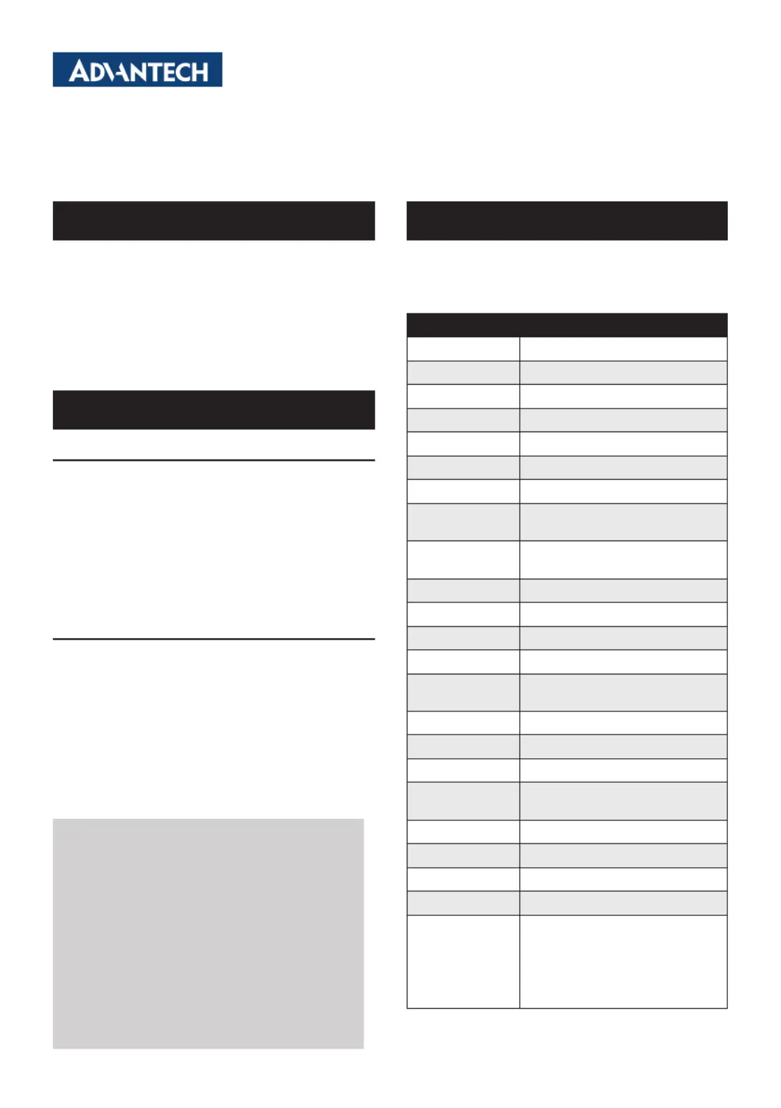
Connectors
Part ReferenceFunction
SHBA1 ~ SHBD1PICMG 1.3 CPU board slot
PPCIEX4_1PCIe p1-x4 with PCIe x16 slot
P1PCIEX16_1~5PCIe x16 slot
P2PCIEX16_1~5PCIe x16 slot
EATXPWR1ATX 2.0 24-pin power connector
EATPWR1AT 12-pin Power connector
ATX12V1
ATX 12 V Auxiliary 4-pin power
connector
ATX12V2
ATX 12 V Auxiliary 4-pin power
connector
EATX12V1ATX 12 V 8-pin power connector
EATX12V2ATX 12 V 8-pin power connector
PWR3V13.3 V Auxiliary power connector
PWR3V23.3 V Auxiliary power connector
PWR_4P1
ATX 5V & 12V 4-pin power con-
nector
VOLT1Alarm board
FAN1 ~ FAN7Fan connectors
FANDEC1Fan speed detect connector
SMBUS1 ~
SMBUS2
Chassis sensor board connectors
JFP1Power and reset button connector
IPMB1IPMB connector
USB12USB connector
USB34USB connector
PSON2
ATX feature Connector (5 VSB,
PSON) for Advantech redundant
power supply: 1757001757,
1757001760, 1757001758,
1757001761, 1757001759,
1757001677
Connectors and Jumpers Packing List
For more information on this and other Advantech
products, please visit our website at:
http://www.advantech.com
http://www.advantech.com/eplatform
For technical support and service, please visit our
support website at:
http://www.advantech.com/support/
This manual is for PCE-5B12-00A1E.
Part No. 20065B1200
Printed in China
Edition 1,
May 2013
Specications
Produktspezifikationen
| Marke: | Advantech |
| Kategorie: | Nicht kategorisiert |
| Modell: | PCE-5B12 |
Brauchst du Hilfe?
Wenn Sie Hilfe mit Advantech PCE-5B12 benötigen, stellen Sie unten eine Frage und andere Benutzer werden Ihnen antworten
Bedienungsanleitung Nicht kategorisiert Advantech

3 April 2026
3 April 2026
3 April 2026
2 April 2026
1 April 2026
24 Februar 2026
3 Februar 2026
2 Februar 2026
2 Februar 2026
2 Februar 2026
Bedienungsanleitung Nicht kategorisiert
Neueste Bedienungsanleitung für -Kategorien-
3 April 2026
3 April 2026
3 April 2026
3 April 2026
3 April 2026
3 April 2026
3 April 2026
3 April 2026
3 April 2026
3 April 2026