AMX DGX3200-ENC Bedienungsanleitung
AMX Nicht kategorisiert DGX3200-ENC
Lies die bedienungsanleitung für AMX DGX3200-ENC (2 Seiten) kostenlos online; sie gehört zur Kategorie Nicht kategorisiert. Dieses Handbuch wurde von 46 Personen als hilfreich bewertet und erhielt im Schnitt 4.7 Sterne aus 9 Bewertungen. Hast du eine Frage zu AMX DGX3200-ENC oder möchtest du andere Nutzer dieses Produkts befragen? Stelle eine Frage
Seite 1/2
Overview
EnovaDGX100SeriesDigitalMediaSwitchersareavailableinvariousconfigurationsin
increments of four up to 8x8, 16x16, 32x32, and 64x64. Therefore, the illustrations in
this guide may differ from the model(s) purchased. Each enclosure contains an
integrated NetLinx Central Control Processor. For complete documentation (including
system and board specifications and supported resolutions), see the Hardware
ReferenceManual – EnovaDGX 100 SeriesDigitalMediaSwitchersatwww.amx.com.
Installation
Rack Mounting
CAUTION:Topreventoverheating,avoidplacinghighheat-producingequipmentdirectly
above/belowenclosure.The system requires a minimum of 1 empty rack unit above and
below(3 emptyrack units are recommended).Verifythat the openings on the sides and
top of the enclosure are not blocked and do not have restrictedairflow.
To rack mount a DGX 800/1600/3200 enclosure (3200 requires 2 people min.):
1. Position enclosure in rack and secure it with rack mounting screws.
* When fully loaded, the Enova DGX 3200 weighs approximately 73 lbs (33.1 kg).
To rack mount a DGX 6400 enclosure (requires 3 people minimum):
1.
Whileshippingbox is stillon thepallet, cutandremoveouter straps.
2.
Removecardboardtray fromtopofshippingbox (notewheelsonbox).
3.
Liftboxoffpallet.TheDGX6400weighsapproximately150lbs(68.0kg)fully
loaded. Ensure all parties involved in lifting are prepared and follow local
requirements.
4.
Unlock4 latches onsidesofshipping box.Lift topof boxstraightup andset
aside.
5.
Attach2 handles providedforlifting;use 4 of 6 holesonside,in frontorrear
position.
6.
Usingbottomof shippingbox,rolltheenclosureintoposition.Liftonto temporary
shelf/supportinrack.Alignascloselyaspossibleandthenremoveliftinghandles.
7.
Lift into position and screw in rack earscrews.
Input and Output Boards
Generally, any input board in an Enova DGX Switcher can route signals to any type of
output board; signal format is automatically converted to match output board.
DXLink Twisted Pair Boards (HDCP 1.4) – Inputs and outputs incorporate HDBaseT
technology. Use with DXLink Twisted Pair TX and RX units. Minimum supported cable
type: CAT6 Shielded.
DXLink 4K Twisted Pair Boards (HDCP 1.4) – Inputs and outputs incorporate
HDBaseT technology. Use with DXLink Twisted Pair 4K TX and RX units. Minimum
supported cable type: CAT6A Shielded.
DXLink 4K60 Twisted Pair Boards (HDCP 2.2 & 1.4) – Inputs and outputs incorporate
HDBaseT technology. Use with DXLink 4K60 Twisted Pair TX and RX units. Minimum
supported cable type: CAT6 Shielded.
EDID Note: 4K60 HDMI Input boards ship with a 4K60 4:2:0 EDID as default to
maximize compatibility, to add 4K60 4:2:2 or 4:4:4 support the proper EDID should be
selected per input either through the System Configuration Interface or over ICSP.
AIE Note: 4K60 DXLink Input boards are limited to Audio Extraction when used with AIE
boards, and the 4K60 DXLink Output boards are limited to Audio Insertion when used
with AIE boards.
DXLink Fiber Boards (HDCP 1.4) – DXLink Fiber boards and units are available for
duplex and simplex functionality (with multimode and single mode options for each) for
various system requirements. Use with DXLink Fiber TX and RX units.
DXLink 4K60 Fib
er Boards (HDCP 2.2 & 1.4) – DXLink 4K60 Fiber boards and units
includemultimodeduplex SFP+ modules which can be replaced with single mode SFP+
modules if needed. Use with DXLink 4K60 Fiber TX and RX units.
Recommended – Fasten cable management bars with 2 screws on one end of board
and 1 screw at other (long part of bar is to right of holes); do not over tighten (FIG. 2
left). DGX 3200 only – Numbering plate must be removed to install bar. Plate can be
reinstalledpostinstallation.WARNING:DXLinkFiberunits use lasertransceivers,which
are Class 1 Eye Safe per IEC 60825-1/CDRH requirements. Class 1 category indicates
that invisible laser used is safe; we recommend avoiding direct eye exposure when
usingany opticalfiberproducts.CAUTION:DXLinkFiberBoards – we recommendusing
the provided cable management bars or another type of cable management system to
avoid damage to fibercables.
IMPORTANT: If not using auto-setup, DIP switches must be set on DXLink Transmitter
and Receiver Modules before units are cabled to the switcher via their boards. For
information on DXLink Transmitters and Receivers, see the unit’s “Quick Start Guide.”
Audio Switching Boards (ASB) – Supports audio breakaway and downmixing for
embeddedorinsertedaudio with Digital Signal Processing capabilities on everyoutput.
Dante™ Audio Switching Board (ASB-DAN) – Supports connection to Audinate’s Dante
network, audio breakaway, and audio downmixing for embedded or inserted audio withDigital
Signal Processing capabilities on everyoutput.
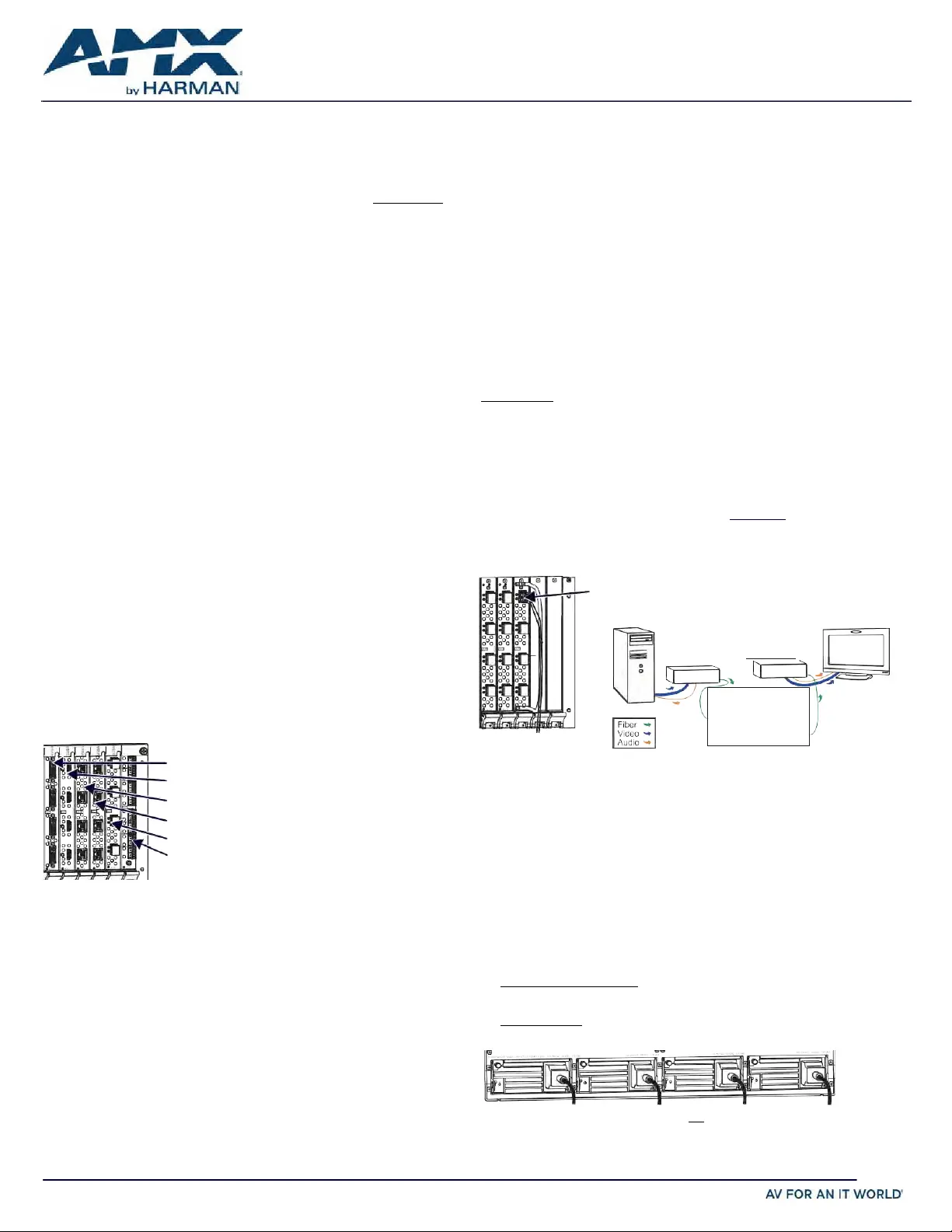
DXLink Fiber connector
(ensure it seats firmly
normally a click isheard)
NOTE: Avoid network loops (created
when enclosure and 1 or more TX/RX
units in a system are both connected
to a common LAN).
Audio Insert/Extract (AIE) Board – AIE Boards are shipped with all of their insert/
extract DIP switches enabled and set to extract audio. If the system’s audio
configuration requires audio insertion on one or more connectors, the board(s) will
need to be removed from the enclosure and DIP switches set to insert audio before the
board(s) are returned to the enclosure.
System Setup
DXLink Fiber TX
DXLink Fiber RX
DVI Board
HDMI / HDMI 4K / 4K60 Board
DXLink TP 4K Board
DXLink TP Board
NOTE: System setup for
DXLink Twisted Pair Boards
is similar to FIG. 2 right,
except with DXLink Twisted
Pair TXs and RXs installed
between the DXLink Boards
and the source and
FIG. 2
DXLINK FIBER CABLE ATTACHED TO INPUT SYSTEM SETUP WITH DXLINK FIBER
Audio EDID Settings
HDMI, DVI, DXLink Twisted Pair Boards ship with a basic audio EDID configuration.
DXLink Fiber Boards obtain EDIDs upon connection to their Transmitters. To optimize
audio for your system, you may need to change the EDID settings using the System
Configuration interface. For information, see the manual.
DXLink Fiber Board
Audio SwitchingBoard
FIG. 1 HDMI DVI DXLINK AND ASB BOARDS SHOWN
destinationdevices.
Applying Power and Startup
DGX 800/1600/3200 systems each have two power supplies; DGX 6400 has four.
NOTE: Using a surge protector and/or an AC line conditioner is recommended.
IMPORTANT: If system is used to power DXLink Twisted Pair TXs/RXs, use the “Enova
DGX 100-Series Configuration Tool” at www.amx.com/enova to calculate power draw.
4K60 HDMI boards (HDCP 2.2 & 1.4) - Inputs and outputs incorporate HDMI® 2.0
technology and route high-resolution HDMI or DVI signals with or without HDCP.
EDID Note: 4K60 HDMI Input boards ship with a 4K30 EDID as default to maximize
compatibility, to add 4K60 support the 4K60 EDID should beselected per input either
through the System Configuration Interface or over ICSP.
AIE Compatibility Note: 4K60 HDMI Input boards are limited to Audio Extraction when
used with AIE boards,andthe4K60 HDMIOutput boardsare limitedto Audio Insertion
whenusedwith AIEboards.
HDMI and 4K HDMI Boards (HDCP 1.4) – HDMI® connectors route high-resolution
HDMI or DVI signals with or without HDCP. For single-link DVI signals, use a cable
adapter.
DVI Boards (HDCP 1.4) – Inputs and outputs are HDMI compatible.
NOTE: If an HDCP signal is switched from an HDMI, HDMI 4K, or DVI Output Board to a
destination which does not support HDCP, display of a dark red image indicates
authenticationfailure.HDMI4K60OutputBoardsdoNOTprovidea red-screenandwill
continuetoattemptauthentication.ForHDCPsignalsswitchedviaDXLinkhardware,an
orange image indicates authenticationfailure.
Enova DGX 6400 only - If two or more power supplies are not receiving power, the
CPU and the control panel will continue to operate. However, input and output boards
will become inoperable and the system will not send or receive signals until at least
three power supplies resume functional status.
For proper redundant operations, all power supplies must be powered at all times.
•
EnovaDGX800/1600/3200– Cableprimary powerfeed tooutletconnected to
one 20 A circuit breaker. Cable redundant power feed to outlet connected to a
second 20 A circuitbreaker.
•
EnovaDGX6400 - ToprovideadequatepowerforanN+1redundant application,
connect each of the four power supplies to its owncircuit.
FIG. 3 POWER CORDS MUST BE PLUGGED INTO ALLPOWER RECEPTACLES (DGX 6400 SHOWN)
QUICK START GUIDE
Enova DGX 100 Series Digital Media Switchers
Enova
DGXSwitcher
DXLink Fiber Input
DXLink Fiber Output
Produktspezifikationen
| Marke: | AMX |
| Kategorie: | Nicht kategorisiert |
| Modell: | DGX3200-ENC |
Brauchst du Hilfe?
Wenn Sie Hilfe mit AMX DGX3200-ENC benötigen, stellen Sie unten eine Frage und andere Benutzer werden Ihnen antworten
Bedienungsanleitung Nicht kategorisiert AMX

18 September 2025
18 September 2025
18 September 2025
17 September 2025
17 September 2025
17 September 2025
16 September 2025
15 September 2025
15 September 2025
15 September 2025
Bedienungsanleitung Nicht kategorisiert
Neueste Bedienungsanleitung für -Kategorien-
3 April 2026
3 April 2026
3 April 2026
3 April 2026
3 April 2026
3 April 2026
3 April 2026
3 April 2026
3 April 2026
3 April 2026