AMX MA-AGLK-07 Bedienungsanleitung
AMX Nicht kategorisiert MA-AGLK-07
Lies die bedienungsanleitung für AMX MA-AGLK-07 (2 Seiten) kostenlos online; sie gehört zur Kategorie Nicht kategorisiert. Dieses Handbuch wurde von 23 Personen als hilfreich bewertet und erhielt im Schnitt 4.2 Sterne aus 6 Bewertungen. Hast du eine Frage zu AMX MA-AGLK-07 oder möchtest du andere Nutzer dieses Produkts befragen? Stelle eine Frage
Seite 1/2
QUICKSTARTGUIDE
MA‐AGLK‐07
AngledMountKitforModeroG5Series
Wall‐mountTouchPanels&SchedulingPanels
MA‐AGLK‐07AngleMountKits
TheMA‐AGLK‐07AngleMountKits(FIG.1)aredesignedtomountModeroG5SeriesWall
MountTouchPanelsandAMXRoomBookSchedulingPanels(7”)intostandardsizedsingle
andgangdoubleboxesinAustralia.theUS,EU,UKandPleasenotetheAMK2AnyMountKit
maybeshowninim
ages,butprocedureisthesamefortheanglemount.
FIG. 1
MA‐AGLK‐07
ModelsAvailable/PanelCompatibility
TheAngleMountKitisavailabletoaccommodate7”ModeroG5Series(wallmount,
landscape),7”ModeroSSeries,SeriesAMXAcendoBookandAMXRoomBookScheduling
TouchPanels:
MODELSAVAILABLE/PANELCOMPATIBILITY
AngleMountKit
Forusewith:
MA‐AGLK‐07
(FG2265‐35)
•G5MD‐702(FG5969‐55BL):7"ModeroSeriesLandscapeWallMountTouch
Panel
•SMSD‐‐701L2(FG2265‐32):7"ModeroSeriesLandscapeWallMountTouch
Panel
•ACB‐2107(FG4221‐07):7”AMXAcendoBookSchedulingTouchPanel
•RMBK‐701(FG2265‐37):7”AMXRoomBookSchedulingTouchPanel
“AGLK”AngleMountKits
TheMA‐‐AGLK207AngleMountKitsareintendedforusewithModeroG5touchpanels,as
wellassecond‐generation‐“L2”ModeroSSeries(Landscape/WallMount),andAMXAcendo
Book&AMXRoomBookSchedulingtouchpanels.Theyconvenientlyplacethetouchpanel
ata15°upwardangleforeasyrea
dability,idealformountingatalowerheighttocomply
withmanyADArequirements.
Pleasenotethesecannotbeusedupsidedowntocreatea15°downwardanglemount.
ProductSpecifications
PRODUCTSPECIFICATIONS
DimensionsHWD:
•”xxxMA‐‐AGLK07:3.976.74”1.76”(100.84mm171.20mmx44.70mm)
Weight:
•MA‐‐AGLK07:0.1lbs(45.36g)
Included
Accessories:
•BackBox(5107643‐00)
•Gasket,Foam(66‐2265‐29)
•XScrew,M3.530mm,PFH,ClearZinc(4)(80‐1620‐04)
•XScrew,#6‐321.25,PFH,TypeF,ClearZinc(4)(80‐1700‐09)
InstallationKitoftheAngleMount
TheAngleMountKitsaredesignedtoutilizeexistingornewlyinstalledgangboxes,withanew
backbackboxtoreplacetheboxincludedwiththetouchpanel.ToinstallanAngleMountKit
anditsaccompanyingtouchpanel:
1.Beforestartingthetheinstallation,ensurethatEthernetcablehasbeenpulledtogang
box,andthatallappropriatePowerOverEthernet(PoE)injectorshavebeenconnected
tothetothecablegoinggangbox.
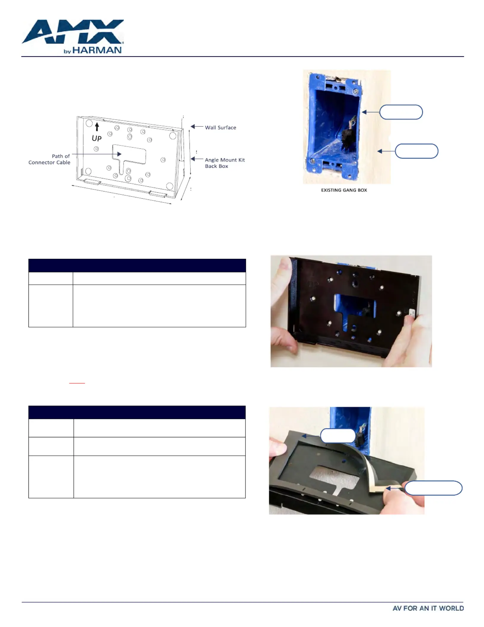
2.Ifthegangboxalreadyhasanexistingfixtureordeviceinstalledinit,removethefixture
ordevicetoexposethegangbox(FIG.2).
3.PullEthernetthecableintothegangbox,makingsurethatthemaleRJ‐45connectoris
accessiblewithinthegangbox.
4.Matchthethethethescrewconnectorholesongangboxwithholesinbackbox(FIG.
3).
•TheAnyMountKitbackboxhasmultipleholestoallowforsingleordoublegangbox
design,designsandforstandardgangboxfromtheUS,UK,EUandAustralia.
•Examinehowthebackboxrestsonthegangbox‐lookforgapsbetweenthebackbox
andthewallsurface.
FIG. 3
TESTINGTHETHEALIGNMENTOFBACKBOXSCREWHOLES.
•Ifthegapbetweenthewallandthebackboxisexcessive,orofiftheinstallationthe
backboxexposestoomuchofthethegangbox,youmayapplyoptionalfoamgasket
()66‐‐226529tothebackofthebackbox.Peeltheadhesivebackingoffth
egasketand
carefullyapplyittothebackboxsurface(FIG.4).
•
FIG. 4
APPLYINGTHETOTHEOPTIONALFOAMGASKETBACKBOX.
5.Oncethepropermountingpositionofthebackboxisconfirmed,attachthebackboxto
thegangbox,usingeitherthescrewsusedwiththeoriginalfixtureordeviceorwiththe
includedscrewsintheAngleMountKit(FIG.5).
WARNING:Becarefulnottoover‐tightenthescrews‐thiscanbowordamagethe
backbox.
15
º
4.2”
2”
7”
FIG. 2
Gangbox
Wallsurface
Adhesivebacking
Gasket
Produktspezifikationen
| Marke: | AMX |
| Kategorie: | Nicht kategorisiert |
| Modell: | MA-AGLK-07 |
Brauchst du Hilfe?
Wenn Sie Hilfe mit AMX MA-AGLK-07 benötigen, stellen Sie unten eine Frage und andere Benutzer werden Ihnen antworten
Bedienungsanleitung Nicht kategorisiert AMX

18 September 2025
18 September 2025
18 September 2025
17 September 2025
17 September 2025
17 September 2025
16 September 2025
15 September 2025
15 September 2025
15 September 2025
Bedienungsanleitung Nicht kategorisiert
Neueste Bedienungsanleitung für -Kategorien-
3 April 2026
3 April 2026
3 April 2026
3 April 2026
3 April 2026
3 April 2026
3 April 2026
3 April 2026
3 April 2026
3 April 2026