Broan L400K Bedienungsanleitung
Broan
Ventilator
L400K
Lies die bedienungsanleitung für Broan L400K (12 Seiten) kostenlos online; sie gehört zur Kategorie Ventilator. Dieses Handbuch wurde von 13 Personen als hilfreich bewertet und erhielt im Schnitt 4.5 Sterne aus 7 Bewertungen. Hast du eine Frage zu Broan L400K oder möchtest du andere Nutzer dieses Produkts befragen? Stelle eine Frage
Seite 1/12
Pa
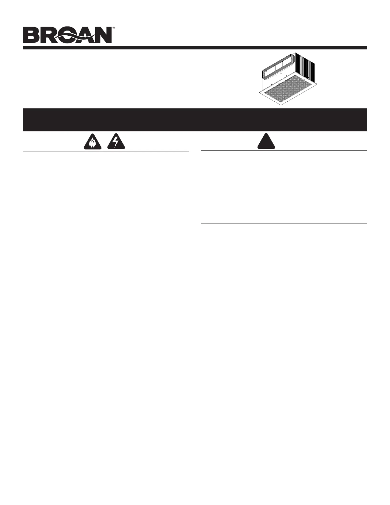
MODELS L400K • L500K
LOSONE SELECT
®
VENTILATORS
Ceiling/Wall Mount 120V
READ AND SAVE THESE INSTRUCTIONS
Page 1
Installer: Leave this manual with
the homeowner.
Homeowner: Use and Care
information on page 3.
!
WARNING
TO REDUCE THE RISK OF FIRE, ELECTRIC SHOCK, OR INJURY
TO PERSONS, OBSERVE THE FOLLOWING:
1. Use this unit only in the manner intended by the manufacturer. If
you have questions, contact the manufacturer at the address or
telephone number listed in the warranty.
2. Before servicing or cleaning unit, switch power off at service panel
and lock the service disconnecting means to prevent power from
being switched on accidentally. When the service disconnecting
means cannot be locked, securely fasten a prominent warning
device, such as a tag, to the service panel.
3. Installation work and electrical wiring must be done by a qualifi ed
person(s) in accordance with all applicable codes and standards,
including fi re-rated construction codes and standards.
4. Suffi cient air is needed for proper combustion and exhausting of
gases through the fl ue (chimney) of fuel burning equipment to
prevent backdrafting. Follow the heating equipment manufacturer’s
guideline and safety standards such as those published by the
National Fire Protection Association (NFPA), and the American
Society for Heating, Refrigeration and Air Conditioning Engineers
(ASHRAE), and the local code authorities.
5. When cutting or drilling into wall or ceiling, do not damage electrical
wiring and other hidden utilities.
6. Ducted fans must always be vented to the outdoors.
7. To reduce the risk of fi re, use only metal ductwork.
8. If this unit is to be installed over a tub or shower, it must be marked
as appropriate for the application and be connected to a GFCI
(Ground Fault Interrupter) - protected branch circuit.
9. Never place a switch where it can be reached from a tub or
shower.
TO REDUCE THE RISK OF A RANGE TOP GREASE FIRE:
1. Never leave surface units unattended at high settings. Boilovers
cause smoking and greasy spillovers that may ignite. Heat oils
slowly on low or medium settings.
2. Always turn hood ON when cooking at high heat or when cooking
fl aming foods.
3. Clean ventilating fans frequently. Grease should not be allowed to
accumulate on fan or fi lter.
4. Use proper pan size. Always use cookware appropriate for the size
of the surface element.
TO REDUCE THE RISK OF INJURY TO PERSONS IN THE EVENT OF
A RANGE TOP GREASE FIRE, OBSERVE THE FOLLOWING:*
1. SMOTHER FLAMES with a close-fi tting lid, cookie sheet, or metal
tray, then turn off the burner. BE CAREFUL TO PREVENT BURNS.
If the fl ames do not go out immediately, EVACUATE AND CALL
THE FIRE DEPARTMENT.
2. NEVER PICK UP A FLAMING PAN - You may be burned.
3. DO NOT USE WATER, including wet dishcloths or towels - a violent
steam explosion will result.
4. Use an extinguisher ONLY if:
A. You know you have a Class ABC extinguisher and you already
know how to operate it.
B. The fi re is small and contained in the area where it started.
C. The fi re department is being called.
D. You can fi ght the fi re with your back to an exit.
*Based on “Kitchen Firesafety Tips” published by NFPA.
CAUTION
1. For general ventilating use only. Do not use to exhaust hazard-
ous or explosive materials and vapors.
2. To avoid motor bearing damage and noisy and/or unbalanced
impellers, keep drywall spray, construction dust, etc. off power
unit.
3. Please read specifi cation label on product for further information
and requirements.
TABLE OF CONTENTS
This manual is divided into sections as follows:
“TYPICAL INSTALLATION”
This section shows a common installation in new and existing,
frame construction.
- Mounting (new construction)
- Mounting (existing construction)
- Wiring
- Ducting (horizontal blower discharge)
“MOUNTING OPTIONS”
“WIRING OPTIONS”
-Wiring Plate Position
“DUCTING OPTIONS”
- Blower Discharge Positions
- Ducting (vertical blower discharge)
“USE AND CARE”
“SERVICE PARTS”
“WARRANTY”
Produktspezifikationen
| Marke: | Broan |
| Kategorie: | Ventilator |
| Modell: | L400K |
Brauchst du Hilfe?
Wenn Sie Hilfe mit Broan L400K benötigen, stellen Sie unten eine Frage und andere Benutzer werden Ihnen antworten
Bedienungsanleitung Ventilator Broan

21 Dezember 2025
19 Dezember 2025
19 Dezember 2025
19 Dezember 2025
18 Dezember 2025
18 Dezember 2025
18 Dezember 2025
18 Dezember 2025
17 Dezember 2025
17 Dezember 2025
Bedienungsanleitung Ventilator
- Beper
- Milwaukee
- Omega Altise
- Casablanca
- Vivax
- BLUEPALM
- Khind
- SEPA
- Meaco
- Grunkel
- Trebs
- Bomann
- Mirpol
- Küppersbusch
- Aspes
Neueste Bedienungsanleitung für -Kategorien-
21 Januar 2026
20 Januar 2026
20 Januar 2026
20 Januar 2026
19 Januar 2026
19 Januar 2026
19 Januar 2026
18 Januar 2026
17 Januar 2026
17 Januar 2026