Broan L900L Bedienungsanleitung
Broan
Ventilator
L900L
Lies die bedienungsanleitung für Broan L900L (12 Seiten) kostenlos online; sie gehört zur Kategorie Ventilator. Dieses Handbuch wurde von 38 Personen als hilfreich bewertet und erhielt im Schnitt 4.4 Sterne aus 19.5 Bewertungen. Hast du eine Frage zu Broan L900L oder möchtest du andere Nutzer dieses Produkts befragen? Stelle eine Frage
Seite 1/12
Pa
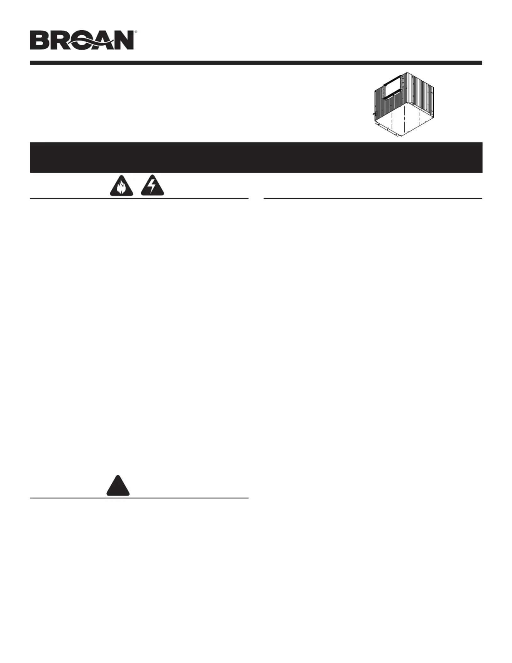
MODELS • L900L • L1500L
!
WARNING
TO REDUCE THE RISK OF FIRE, ELECTRIC SHOCK, OR IN-
JURY TO PERSONS, OBSERVE THE FOLLOWING:
1. Use this unit only in the manner intended by the manufacturer.
If you have questions, contact the manufacturer at the address
or telephone number listed in the warranty.
2. Before servicing or cleaning unit, switch power off at service
panel and lock the service disconnecting means to prevent
power from being switched on accidentally. When the service
disconnecting means cannot be locked, securely fasten a promi-
nent warning device, such as a tag, to the service panel.
3. Installation work and electrical wiring must be done by a quali-
fied person(s) in accordance with all applicable codes and stan-
dards, including fire-rated construction codes and standards.
4. Sufficient air is needed for proper combustion and exhausting of
gases through the flue (chimney) of fuel burning equipment to
prevent backdrafting. Follow the heating equipment
manufacturer’s guideline and safety standards such as those
published by the National Fire Protection Association (NFPA),
and the American Society for Heating, Refrigeration and Air Con-
ditioning Engineers (ASHRAE), and the local code authorities.
5. When cutting or drilling into wall or ceiling, do not damage elec-
trical wiring and other hidden utilities.
6. Ducted fans must always be vented to the outdoors.
7. To reduce the risk of fire, use only metal ductwork.
8. If this unit is to be installed over a tub or shower, it must be
marked as appropriate for the application and be connected to a
GFCI (Ground Fault Interrupter) - protected branch circuit.
9. Never place a switch where it can be reached from a tub or
shower.
10. This unit must be grounded.
CAUTION
1. For general ventilating use only. Do not use to exhaust hazard-
ous or explosive materials and vapors.
2. To avoid motor bearing damage and noisy and/or unbalanced
impellers, keep drywall spray, construction dust, etc. off power
unit.
3. If ventilator is installed in an unconditioned space (such as
an attic): Surround the ventilator with thermal insulation - to
minimize possible condensation.
4. Please read specification label on product for further informa-
tion and requirements.
LOSONE SELECT
®
VENTILATORS
In-Line • 120V
READ AND SAVE THESE INSTRUCTIONS
TABLE OF CONTENTS
This manual is divided into sections as follows:
• “TYPICAL INSTALLATION”
This section shows a common installation in new and existing,
frame construction.
- Mounting (new construction)
- Mounting (existing construction)
- Wiring
- Ducting (straight-through blower discharge)
• “MOUNTING OPTIONS”
• “WIRING OPTIONS”
-Wiring Plate Position
• “DUCTING OPTIONS”
- Blower Discharge Positions
- Ducting (right-angle blower discharge)
• “USE AND CARE”
• “SERVICE PARTS”
• “WARRANTY”
Installer: Leave this manual with the homeowner.
Homeowner: Use and Care information on page 3.
Page 1
Produktspezifikationen
| Marke: | Broan |
| Kategorie: | Ventilator |
| Modell: | L900L |
Brauchst du Hilfe?
Wenn Sie Hilfe mit Broan L900L benötigen, stellen Sie unten eine Frage und andere Benutzer werden Ihnen antworten
Bedienungsanleitung Ventilator Broan

21 Dezember 2025
19 Dezember 2025
19 Dezember 2025
19 Dezember 2025
18 Dezember 2025
18 Dezember 2025
18 Dezember 2025
18 Dezember 2025
17 Dezember 2025
17 Dezember 2025
Bedienungsanleitung Ventilator
- White Shark
- Heller
- Kanlux
- Infiniton
- Gembird
- Itho
- Klarstein
- SPC
- V-TAC
- Arcoaire
- Midea
- Javalo Elf
- Fantech
- Hotpoint
- SEPA
Neueste Bedienungsanleitung für -Kategorien-
21 Januar 2026
20 Januar 2026
20 Januar 2026
20 Januar 2026
19 Januar 2026
19 Januar 2026
19 Januar 2026
18 Januar 2026
17 Januar 2026
17 Januar 2026