Camille Bauer SINEAX V620 Bedienungsanleitung
Camille Bauer Audio/Video-Konverter SINEAX V620
Lies die bedienungsanleitung für Camille Bauer SINEAX V620 (2 Seiten) kostenlos online; sie gehört zur Kategorie Audio/Video-Konverter. Dieses Handbuch wurde von 29 Personen als hilfreich bewertet und erhielt im Schnitt 4.9 Sterne aus 4 Bewertungen. Hast du eine Frage zu Camille Bauer SINEAX V620 oder möchtest du andere Nutzer dieses Produkts befragen? Stelle eine Frage
Seite 1/2
SINEAX V620 DEUTSCH 1/4SINEAX V620 DEUTSCH 2/4SINEAX V620 DEUTSCH 3/4
SINEAX V620 DEUTSCH 4/4
SINEAX V620
Universal-Signalkonverter
für mA, V, TC, RTD, Ω
163 02210.17
Allgemeine Eigenschaften
• Universal-Eingang, Spannung, Strom, Thermoelemente, Widerstandsthermo-
meter, Potentiometer, Rheostat, veränderbarer Widerstand 2-Leiter.
• Stromversorgung des Sensors in 2-Draht-Technik: 20 V DC stabilisiert, max.
20 mA, vor Kurzschluss geschützt.
• Messung und Rückübertragung auf galvanisch getrenntem Analogausgang mit
aktivem/passivem Ausgang für Spannung und Strom.
• Auswahl mittels DIP-Schalter von: Eingangsart, START-END, Ausgangsmodus
(Null ermittlung, Skalenumkehrung), Ausgangsart (mA oder V).
• Anzeige des Anliegens der Stromversorgung, Skalenüberschreitung oder Ein-
richtfehler bzw. Alarmstatus auf der Frontseite.
• Ausgang für Alarmkontakt mit Relais (Spst), mittels PC einrichtbar.
• STROBE-Eingang zur Aktivierung des Analogausgangs zur Steuerung einer
SPS (alternativ zum Alarmkontakt).
• Möglichkeit zur Programmierung des Skalenanfangs- und endwertes, der
zusätzlichen Eingangsarten, der Wurzelbildung, des Filters, des Burn-out usw.
mittels PC.
• Galvanische 3-Wege-Trennung: 1500 V AC.
Technische Daten
Spannungsversorgung
10…40 V DC, 19…28 V AC, 50…60 Hz, max. 2,5 W; 1,6 W
bei 24 V DC mit Ausgang 20 mA
Eingang Spannung
Zweipolig von 75 mV bis zu 20 V in 9 Skalen,
Eingangs impedanz 1 MΩ, max. Auflösung 15 Bit + Zeichen
Eingang Strom
Zweipolig bis zu 20 mA, Eingangsimpedanz 50 Ω,
max. Auflösung 1 µA
Eingang Widerstands-
thermometer (RTD)
PT100, PT500, PT1000,
Ni100, KTY81, KTY84, NTC
Messung mit 2, 3 oder 4 Drähten, Auslösestrom 0,56 mA,
Auflösung 0,1 °C, automatische Messung von Kabelunter-
brechung oder RTD. Für NTC Widerstandswert < 25 kΩ.
KTY81, KTY84 und NTC nur über Software einrichtbar
Eingang
Thermoelement
Typ J, K, R, S, T, B, E, N; Auflösung 2,5 µV, automatische Messung
der Unterbrechung TC, Eingangsimpedanz >5 MΩ
Eingang ReglerSkalenendwert min. 500 Ω, max. 25 kΩ
Eingang Potentiometer
Auslösespannung 300 mV, Eingangsimpedanz > 5 MΩ,
Potentiometer wert von 500 Ω bis 100 kΩ (mit Hilfe eines parallel
geschalteten Widerstandes von 500 Ω)
Bemusterungsfrequenz
Variabel von 240 sps bei Auflösung 11 Bit + Zeichen bis
15 sps bei Auflösung 15 Bit + Zeichen (typische Werte)
Reaktionszeit
35 ms bei Auflösung 11 Bit, 140 ms bei Auflösung 16 Bit
(Messung von Spannung, Strom, Potentiometer)
Ausgang
I: 0…20/4…20 mA, max. Lastwiderstand 600 Ω
V: 0…5/0…10/1…5/2…10 V, min. Lastwiderstand 2 kΩ
Auflösung 2,5 µA / 1,25 mV
Relais Ausgang (spst)Schaltleistung: 1 A … 30 V DC / V AC
Umgebungsbedingungen
Temperatur: -20…60 °C, Feuchtigkeit min. 30%, max. 90%
bei 40 °C ohne Kondensation (siehe Abschnitt «Installations-
vorschriften»)
Fehler in Bezug auf den
maximalen Messbereich
Kalibrierfehler
Temperatur-
koeffizient
Linearitäts-
fehler
Anderes
Eingang für Spannung/
Strom
0,3%
0,01% / °K
0,05%EMI: < 1%
Eingang für PTC J, K, E, T, N0,5%0,2 °C
+(2) EMI: <1%Eingang für PTC R, S0,5%0,5 °C
Eingang für PTC B (4)0,5%1,5 °C
Ausgleich Kaltverbindung2 °C Umgebungstemperatur 0 bis 50 °C
Potentiometer/Widerstand0,3%
0,01% / °K
0,1%EMI: < 1%
Eingang Heizwiderstand (5)0,3%
t > 0°C 0,02%
t < 0°C 0,05%
(1) EMI: < 1%
Spannungsausgang (3)0,3%0,01%
DatenspeicherEEPROM für alle Konfigurationsdaten; Speicherzeit 40 Jahre
Das Instrument entspricht folgenden Standards:
EN 61000-6-4/2007 (elektromagnetische Störungen, Industrielle Umgebung)
EN 61000-6-2/2005 (elektromagnetische Unempfindlichkeit, industrielle Umgebung)
EN 61010-1/2001 (Sicherheit)
Alle Schaltkreise müssen mit einer doppelten Isolierung gegenüber gefährliche Spannung
führenden Schaltkreisen versehen werden. Der Transformator zur Stromversorgung muss dem
Standard EN 60742: Isolier- und Sicherheitstransformatoren, Vorschriften entsprechen.
Anmerkungen:
– Benutzen mit Kupferleitung
– Benutzen in Verschmutzungsgrad 2 Umgebung
– Spannungsversorgung muss Klasse 2 sein
– Bei Verwendung eines galvanisch getrennten Netzteils sollte eine Sicherung von 2,5 A max.
davor installiert werden.
(1) Einfluss des Kabelwiderstands 0,005%/Ω, max. 20 Ω
(2) Einfluss des Kabelwiderstands 0,1 µV/Ω
(3) Zu den Fehlern bezüglich des gewählten Eingangs zu summierende Werte
(4) Ausgang null für t < 400 °C
(5) Alle auf den Widerstandswert zu berechnenden Fehler
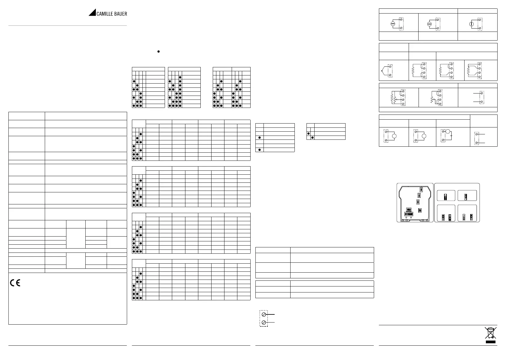
Auswahl des Eingangs
Die Auswahl der Eingangsart erfolgt durch Einrichtung der Gruppe von DIP-
Schaltern SW1 seitlich des Moduls.
Jeder Eingangsart entspricht eine bestimmte Anzahl von Skalenanfangs- und
endwerten, die mit der Gruppe SW2 wählbar sind.
In der nachstehenden Tabelle werden die möglichen Werte für START und END
je nach der gewählten Eingangsart aufgeführt.
In der Tabelle gibt die linke Spalte die Kombination der DIP-Schalter an, die für
die gewählten START und END einzurichten sind.
Anmerkung für alle Tabellen:
Die Beschriftung
zeigt an, dass der DIP-Schalter in der ON-Position ist.
Kein Eintrag bedeutet, dass der DIP-Schalter in der OFF-Position ist!
SW1: EINGANGSARTEN SW2: START/END
EingangsartenEingangsartenSTARTEND
12341234123456
V
Tc K11
Ω/ReglerTc R22
mATc S33
Ni100Tc T44
PT100Tc B55
PT500Tc E66
PT1000Tc N77
Tc JPotentiometer88
SW2
SpannungWiderstand/ReglerStromPotentiometer
STARTENDSTARTENDSTARTENDSTARTEND
1(*)(*)(*)(*)(*)(*)(*)(*)
20 V100 mV0 Ω1 kΩ0 mA1 mA0%40%
3400 mV200 mV0,5 kΩ2 kΩ1 mA2 mA10%50%
41 V500 mV1 kΩ3 kΩ4 mA3 mA20%60%
52 V1 V2 kΩ5 kΩ-1 mA4 mA30%70%
6-5 V5 V5 kΩ10 kΩ-5 mA5 mA40%80%
7-10 V10 V10 kΩ15 kΩ-10 mA10 mA50%90%
8-20 V20 V15 kΩ25 kΩ-20 mA20 mA60%100%
Ni100 (RTD)PT100 (RTD)PT500 (RTD)PT1000 (RTD)
STARTENDSTARTENDSTARTENDSTARTEND
1(*)(*)(*)(*)(*)(*)(*)(*)
2-50 °C20 °C-200 °C50 °C-200 °C0 °C-200 °C0 °C
3-30 °C40 °C-100 °C100 °C-100 °C50 °C-100 °C50 °C
4-20 °C50 °C-50 °C200 °C-50 °C100 °C-50 °C100 °C
50 °C80 °C0 °C300 °C0 °C150 °C0 °C150 °C
620 °C100 °C50 °C400 °C50 °C200 °C50 °C200 °C
730 °C150 °C100 °C500 °C100 °C300 °C100 °C300 °C
850 °C200 °C200 °C600 °C150 °C400 °C200 °C400 °C
Thermoelement JThermoelement KThermoelement RThermoelement S
STARTENDSTARTENDSTARTENDSTARTEND
1(*)(*)(*)(*)(*)(*)(*)(*)
2-200 °C100 °C-200 °C200 °C0 °C400 °C0 °C400 °C
3-100 °C200 °C-100 °C400 °C100 °C600 °C100 °C600 °C
40 °C300 °C0 °C600 °C200 °C800 °C200 °C800 °C
5100 °C400 °C100 °C800 °C300 °C1000 °C300 °C1000 °C
6200 °C500 °C200 °C1000 °C400 °C1200 °C400 °C1200 °C
7300 °C800 °C300 °C1200 °C600 °C1400 °C600 °C1400 °C
8500 °C1000 °C500 °C1300 °C800 °C1750 °C800 °C1750 °C
Thermoelement TThermoelement BThermoelement EThermoelement N
STARTENDSTARTENDSTARTENDSTARTEND
1(*)(*)(*)(*)(*)(*)(*)(*)
2-200 °C50 °C0 °C500 °C-200 °C50 °C-200 °C200 °C
3-100 °C100 °C500 °C600 °C-100 °C100 °C-100 °C400 °C
4-50 °C150 °C600 °C800 °C0 °C200 °C0 °C600 °C
50 °C200 °C700 °C1000 °C100 °C300 °C100 °C800 °C
650 °C250 °C800 °C1200 °C150 °C400 °C200 °C1000 °C
7100 °C300 °C1000 °C1500 °C200 °C600 °C300 °C1200 °C
8150 °C400 °C1200 °C1800 °C400 °C800 °C500 °C1300 °C
(*) START oder END, die im Speicher mittels PC oder Programmiertasten einge-
richtet wurden.
Beliebige Einrichtung von START und END zur Messung
Die Tasten START und END unter der Gruppe der DIP-Schalter SW2 ermögli-
chen das beliebige Einrichten des Skalenanfangs- und endwertes innerhalb des
mit den DIP-Schaltern eingerichteten Messbereichs. Für diesen Vorgang ist ein
geeig neter Signalgenerator erforderlich, der in der Lage ist, die gewünschten
Werte für Skalenende- oder anfang zu liefern.
Dabei ist wie folgt vorzugehen:
1. Richten Sie mit der entsprechenden Gruppe von DIP-Schaltern die gewünsch-
te Eingangsart, sowie START und END für die Messung ein, die den gewünsch-
ten Skalenanfangs- und endwert für die Messung enthalten.
2. Schalten Sie die Stromversorgung am Modul zu.
3. Bringen Sie einen Generator oder Kalibrator für das Signal an, das gemessen
und übertragen werden soll.
4. Richten Sie am Generator den gewünschten Skalenanfangswert ein.
5. Betätigen Sie die Taste START für mindestens 3 s. Ein Blinken der grünen LED
auf der Frontplatte des Instruments zeigt die erfolgte Speicherung des Wertes
an.
6. Wiederholen Sie die Punkte 4 und 5 für den gewünschten Wert END.
7. Entfernen Sie die Stromversorgung des Moduls und stellen Sie die DIP-Schal-
ter der Gruppe SW2 für die Einrichtung der Werte von START und END in die
Position OFF.
Jetzt ist das Modul für den gewünschten Skalenanfangs- und endwert konfigu-
riert. Zu seiner Programmierung, auch für eine andere Eingangsart, genügt es,
den gesamten Vorgang zu wiederholen.
Auswahl des Ausgangs
Die DIP-Schalter mit Nummer 7 und 8 der Gruppe SW2 ermöglichen das ent-
sprechende Einrichten des Ausgangs mit oder ohne Ermittlung von Null, norma-
lem oder umgekehrtem Ausgang. Die Gruppe der DIP-Schalter SW3 ermöglicht
die Auswahl der Ausgangsart.
Anmerkung: Die Einrichtung der DIP-Schalter muss bei nicht gespeistem
Modul erfolgen, wodurch elektrostatische Entladungen vermieden werden,
die zu einer möglichen Beschädigung des Moduls führen können.
SW2AusgangsartSW3Ausgang
712
0…20 mA / 0…10 V
Spannung
4…20 mA / 2…10 VStrom
8
Normal
Umgekehrt
Einrichtung mittels PC
Mittels eines PC und der Software V620 (downloadbar unter
www.camillebauer.com) ist es möglich, ausser dem Skalenanfang und ende
weitere normalerweise unveränderliche Parameter einzurichten.
• Zusätzliche Eingangsarten
• Digitaler Filter (normalerweise nicht inbegriffen)
• Wurzelziehung (normalerweise nicht inbegriffen)
• Negatives Burn-out (normalerweise positiv)
• Alarm (normalerweise als Fehlermeldung eingerichtet)
• Skalenanfang und ende des Analogausgangs
• Wert des Analogausgangs bei einem Fehler
• Unterdrückung bei Netzfrequenz 50/60 Hz (normalerweise auf 50 Hz eingerich-
tet)
• Bemusterungsgeschwindigkeit/Auflösung (normalerweise auf 15 sps/16 Bit
eingerichtet
• Messung mit 3 oder 4 Drähten bei Heizwiderständen (normalerweise auf 3
Drähte eingerichtet
• Auslösung des Alarmrelais bei einem Defekt des Instruments.
Die Anleitung zur Einrichtung und das Anschlusskabel liegen der Software bei,
die als Zubehör zu bestellen ist.
Anzeigen mittels LED auf der Frontseite
Grüne LEDBedeutung
Blinken
(Freq. = 1 Blinkz./s)
Ausserhalb Skala, Burn-out oder Interner Defekt
Blinken
(Freq. = 2 Blinkz./s)
Fehler beim Einrichten der DIP-Schalter
Dauerhaft leuchtendZeigt das Anliegen der Stromversorgung an
Gelbe LEDBedeutung
EingeschaltetAnzeige eines Alarms (Relaiskontakt offen)
AusgeschaltetKein Alarm (Relaiskontakt geschlossen)
Elektrische Anschlüsse
Stromversorgung
Die Versorgungsspannung muss zwischen 10 und
40 V DC (unabhängig von der Polarität), 19 und
28 V AC liegen; siehe auch im Abschnitt «Installa-
tionsvorschriften».
Die Obergrenzen dürfen nicht überschritten
werden, da es sonst zu schweren Schäden am Modul kommen kann. Es
ist notwendig, die Stromversorgungsquelle vor eventuellen Defekten des Moduls
durch eine ausreichend bemessene Sicherung zu schützen.
19 ÷ 28 VAC
10 ÷ 40 VDC
2,5 W max.
2
3
StromeingangSpannungseingang
mA Eingang
11
10
+
mA Eingang (2-Draht)
7
11
+
V Eingang
9
10
+
Die Stromversorgung des
Loop erfolgt über den Sensor
Die Stromversorgung des
Loop erfolgt über das Modul
Eingang
Thermoelement
Eingang Heizwiderstand
NTC, KTY81,
KTY84
PT100, Ni100, PT500, PT1000
mV/TC Eingang
12
10
+
RTD 2-Draht
10
12
9
8
RTD 3-Draht
10
12
9
8
RTD 4-Draht
10
12
9
8
Eingang Potentiometer / ReglerEingang Strobe (7)
10
12
9
8
P
R
10
12
9
8
4
5
+
-
12…24 VDC
Mit Widerstand R = 500 Ω (nicht mitgeliefert), P = 500 Ω ÷ 100 kΩ
Ausgang zur Rückübertragung
Relaisausgang
(10)
Spannung
Erzeugter
Strom (8)
Externe Strom-
versorgung (9)
V Ausgang
6
1
+
V
mA Ausgang
6
1
+
A
+ mA Ausgang
1
6
A
+
4
5
1A - 30 V
(7) Alternativ zum Relaisausgang. Ist von den übrigen Schaltkreisen isoliert
und dient zur Aktivierung des analogen Stromausgangs. Kann für das Mul-
tiplexing eines SPS-Eingangs an V620 verwendet werden. Zur Aktivierung
siehe unter «Einstellungen mit internen Brücken».
(8) Bereits gespeister, aktiver Ausgang zum Anschluss an passive Eingänge.
(9) Nicht gespeister, passiver Ausgang zum Anschluss an aktive Eingänge. Zur
Auswahl siehe unter «Einstellungen mit internen Brücken»
(10) Alternativ zum Eingang STROBE aktiviert. Relais-Öffnerkontakt, bei Alarm
geöffnet.
POSITION DER INTERNEN BRÜCKENEINSTELLUNGENMITINTERNENBRÜCKEN
AKTIVER / PASSIVERAUSGANG
RELAISAUSGANG / STROBE-EINGANG
Relaisausgang
STROBE-Eingang
AktiverAusgang
PassiverAusgang
SW1
SW2
SW3
J3
J9
J1
J9
J9
J3
J1
J3
J1
Installationsvorschriften
Das Modul wurde zur Montage auf DIN-Schiene 46277 in senkrechter Position
entworfen. Für eine optimale Funktionsweise und Dauerhaftigkeit muss eine an-
gemessene Belüftung zu dem/n Modul/en gewährleistet und vermieden werden,
Kanäle oder andere Gegenstände darauf zu stellen, die die Belüftungsschlitze
verschliessen. Vermeiden Sie eine Montage der Module über Wärme erzeugen-
den Geräten. Zu empfehlen ist die Montage im unteren Teil des Schaltkastens.
Erschwerte Betriebsbedingungen
Erschwerte Betriebsbedingungen sind:
• Hohe Versorgungsspannung (> 30 V DC / > 26 V AC).
• Stromversorgung des Eingangssensors.
• Verwendung des Ausgangs für Fremdstrom.
Wenn die Module nebeneinander montiert sind, ist es möglich, dass sie in fol-
genden Fällen um mindestens 5 mm voneinander getrennt werden müssen:
• Bei einer Temperatur des Schaltkastens von über 45 °C und Vorliegen von min-
destens einer der erschwerten Bedingungen.
• Bei einer Temperatur des Schaltkastens von über 35 °C und Vorliegen von min-
destens zwei der erschwerten Bedingungen.
Elektrische Verbindungen
Zur Erfüllung der Immunitätsanforderungen wird der Einsatz von abgeschirmten
Kabeln zum Anschluss der Signale empfohlen. Die Abschirmung muss an eine
Primärerdung für die Instrumentierung angeschlossen werden. Ausserdem ist es
günstig, die Leiter nicht in der Nähe der Kabel zur Leistungsinstallation zu ver-
legen, wie Invertern, Motoren, Induktionsöfen usw.
Tel. +41 56 618 21 11
Camille Bauer Metrawatt AG Fax +41 56 618 21 21
Aargauerstrasse 7 [email protected]
CH-5610 Wohlen/Schweiz www.camillebauer.com
PM1000897 000 02
Produktspezifikationen
| Marke: | Camille Bauer |
| Kategorie: | Audio/Video-Konverter |
| Modell: | SINEAX V620 |
Brauchst du Hilfe?
Wenn Sie Hilfe mit Camille Bauer SINEAX V620 benötigen, stellen Sie unten eine Frage und andere Benutzer werden Ihnen antworten
Bedienungsanleitung Audio/Video-Konverter Camille Bauer

4 September 2025
3 September 2025
3 September 2025
3 September 2025
3 September 2025
Bedienungsanleitung Audio/Video-Konverter
Neueste Bedienungsanleitung für -Kategorien-
29 März 2026
29 März 2026
24 März 2026
22 März 2026
22 März 2026
21 März 2026
21 März 2026
15 März 2026
12 März 2026
6 März 2026