Daytronic 10A79-4 Bedienungsanleitung
Daytronic Nicht kategorisiert 10A79-4
Lies die bedienungsanleitung für Daytronic 10A79-4 (2 Seiten) kostenlos online; sie gehört zur Kategorie Nicht kategorisiert. Dieses Handbuch wurde von 22 Personen als hilfreich bewertet und erhielt im Schnitt 4.0 Sterne aus 7 Bewertungen. Hast du eine Frage zu Daytronic 10A79-4 oder möchtest du andere Nutzer dieses Produkts befragen? Stelle eine Frage
Seite 1/2
For use in System 10 ....... The 10A79-4 is an extremely useful card that can be remotely controlled to provide:
•Real-time capture of analog-signal peak values, both positive and negative. The card will detect and store in analog
(capacitor) memory the most positive and most negative values experienced by a given analog input signal since the input
channel in question was last reset by an appropriate logic “TRACK” command. Each peak value will remain in memory—though
subject to analog decay*— until reapplication of the respective “TRACK” command, or until occurrence of a subsequent more
positive or more negative signal excursion (thus permitting the capture of successively higher maxima or successively lower
minima). You can easily arrange for all positive or negative peaks reported by a 10A79-4’s Channel No. y to be indefinitely
(digitally) held, by entering a CALCULATE (CLC) command of the form CLC x = MAX CHN y or CLC x = MIN CHN y.
•Real-time “MAX minus MIN” measurement (i.e., the real-time difference between the most positive and most negative values
detected for a given analog input signal since the input channel was last reset). This feature, which requires that the input be
set to “MAX-MIN” mode, is particularly useful when you need to know the precise range of an excursive phenomenon like the
runout, wobble, or looseness of a rotating part. If you wish to display a given “MAX-MIN” value for any length of time, without
decay, you can apply a LOCK (LOK) command to the channel in question.
•“TRACK and HOLD” operation for up to four analog signals. Upon release of an input channel’s “TRACK” condition, the
channel will, when set to this mode of operation, instantly freeze its present value in analog memory until reapplication of the
“TRACK” command. If you wish to display a given “held” value for any length of time, without decay, you can apply a LOCK
(LOK) command to the channel in question.
•Buffering of up to four analog signals for continuous, real-time, unscaled output to various external devices.
Each of the 10A79-4’s four analog inputs can be hard-wired to any selected “A-Card” conditioner within the system that has
“Auxiliary Output” provisions.** Derived from each of the four inputs are:
a.two internal SYSTEM DATA CHANNELS: (1) “+PEAK” and (2) either “MAX-MIN” or “–PEAK,” depending on the input’s
mode setting. These channels can be displayed on the system CRT or LCD display, if present, and can be interrogated like any
other standard data channels via the CHANNEL (CHN) command.
b.two ANALOG OUTPUTS: (1) “+PEAK” and (2) “–PEAK.” These can be sent in turn to a stripchart recorder or similar device,
or can serve as fast “real-time” inputs to a PID servo controller. One or both of a given analog input’s data channels (and
corresponding analog outputs) can be easily converted to “TRACK and HOLD” operation, when the input is set to “– PEAK”
mode.
The 10A79-4’s PEAK-CAPTURE, “MAX – MIN,” and/or “TRACK and HOLD” process is completely controlled by logic-level
inputs received at the 10A79-4’s rear I/O Connector from a Model 10AIO-16 or 10BIO-16 Universal Logic I/O Card, or from
an external logic source. There are two logic inputs for each analog input channel: “TRACK / NOT + PEAK” and “TRACK
/ NOT MAX-MIN.” Standard processing functions may be applied to any of the data channels generated by the 10A79-4,
including calculations, dual limit monitoring, etc.
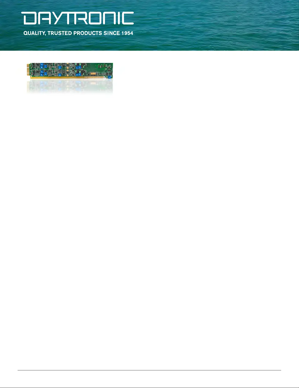
FOUR CHANNEL PEAK - TRACK - HOLD CARD
MODEL 10A79-4
FOUR CHANNEL PEAK - TRACK - HOLD CARD
[“A’ CARD SERIES]
Produktspezifikationen
| Marke: | Daytronic |
| Kategorie: | Nicht kategorisiert |
| Modell: | 10A79-4 |
Brauchst du Hilfe?
Wenn Sie Hilfe mit Daytronic 10A79-4 benötigen, stellen Sie unten eine Frage und andere Benutzer werden Ihnen antworten
Bedienungsanleitung Nicht kategorisiert Daytronic

9 September 2025
8 September 2025
7 September 2025
7 September 2025
7 September 2025
7 September 2025
7 September 2025
7 September 2025
7 September 2025
7 September 2025
Bedienungsanleitung Nicht kategorisiert
Neueste Bedienungsanleitung für -Kategorien-
3 April 2026
3 April 2026
3 April 2026
3 April 2026
3 April 2026
3 April 2026
3 April 2026
3 April 2026
3 April 2026
3 April 2026