For.A HVS-190I Bedienungsanleitung
For.A Nicht kategorisiert HVS-190I
Lies die bedienungsanleitung für For.A HVS-190I (2 Seiten) kostenlos online; sie gehört zur Kategorie Nicht kategorisiert. Dieses Handbuch wurde von 31 Personen als hilfreich bewertet und erhielt im Schnitt 4.3 Sterne aus 2 Bewertungen. Hast du eine Frage zu For.A HVS-190I oder möchtest du andere Nutzer dieses Produkts befragen? Stelle eine Frage
Seite 1/2
HVS190-SETUPGUIDE-E-1.DOCX
HVS-190S/190OU
HVS-190I
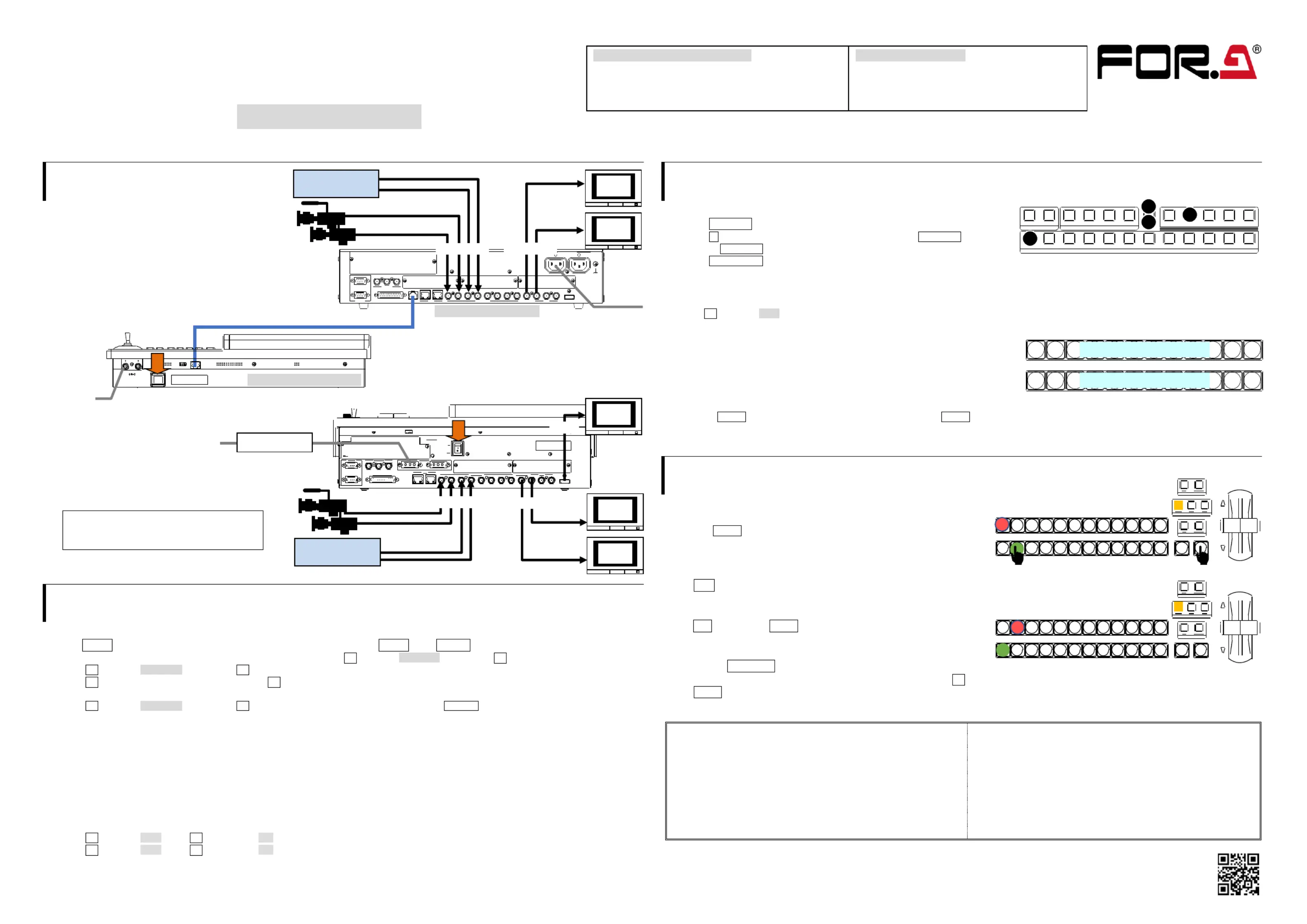
1. Connection
HVS-190S/190 OU
(1) Connect SDI video signal inputs.
(2) Connect SDI video signal outputs.
(3) Connect HVS-S and OU using 190190
the supplied cable with OU. 190
(4) Supply power to HVS-190S using the supplied AC cable.
(5) Supply power to HVS-190OU using the supplied AC adapter.
(6) Turn on power switches on the HVS-S 190
front panel and the 1 rear panel. 90OU
HVS-1 90I
(1) Connect SDI video signal inputs.
(2) Connect SDI video signal outputs.
(3) Connect the AC adapter to the switcher.
(4) Supply AC power to the AC adapter.
Supply AC power after the AC adapter is
connected to the switcher. Otherwise the
switcher internal parts may be damaged.
(5) Turn on the power switch on the rear panel.
2Setup.
Select the System Signal Format
(1) The MENU button on the control panel should blink at power ON. Press MENU, then SETUP.
(2) The [SETUP] menu top page appears in the menu display. Turn to select SYSTEM, then press to display the submenu. F1F1
(3) Turn to select FORMAT, then press to display the submenu. F1F1
(4) Turn to select the signal format, then press Change the aspect ratio and switch timing, as necessary. F1F1.
(5) Press the page up button to return to the [SETUP > SYSTEM] menu.
(6) Turn to select REBOOT, then press A conrmation message will appear. Press TER in the SELECT/KEYPAD block to F1F1. EN
reboot the switcher.
See Sec. 2-2"lecting the Video Format (System Mode)" in the User Manual for more details. . Se
Set Date, Time and Time Zone
Open the [SETUP > SYSTEM > TIME] menu to set date, time and time zone.
See Sec. -1-2. "Date Time Settingsin the User Manual for more details. 17and"
Set the Frame Synchronizer Function to ON if using an internal lock
(1) Open the [SETUP > INPUT > SIGNALmenu. ]
(2) Turn to select IN01. Turn F4 to set FS to . F1ON
(3) Turn to select IN02. Turn F4 to set FS to . Set FS to ON for other inputs. F1ON
See Sec. 7-2. "Frame Synchronizer" in the User Manual for more details.
3Select Output Video.
To Output PVW (Preview) Video from AUX1
(1) Press AUX SEL to turn on the button light.
(2) Press 1 (AUX1) in the bottom row while holding down AUX SEL .
(3) Release AUX SEL.
(4) Press PVW/KOUT to display the PVW video on AUX1 output.
To Output MV (Multi-view) Video from HDMI
(1) Open the [SETUP > OUTPUT > HDMI] menu.
( Turn to select MV1. (Refer to Sec. 2-4-- 2)F12 “Viewing the Multiview Video on the HDMI OUT” in the User Manual for more details.)
To Select the PGM (program) Video / PVW
The PGM bus buttons are used to select the PGM (background) video.
(The PGM video is displayed in the PGM output on the rear panel.)
The PST bus buttons are used to select the (background) video. PVW
Press a button on the PGM or PST bus to see how the output video changes.
Now, press AUTO in the bottom right of the control panel (with BKGD lit). Or move the fader from end to end.
The PGM (AUX1) video images are switched with each other. This is called a "background transition". and PVW
4. Perform Background Transitions
Setup
Select the next video on the PST bus.
Verify that BKGD lights up as shown at right.
If not, press the button to turn on the button light.
To Perform CUT Transitions
Press . The PGM video immediately changes. CUT
To Perform MIX Transitions
Press MIX. Then press AUTO. ( move the fader from end to end.) Or
To Perform Pattern Transitions
Quickly press WIPE/EFF twice.
The [BKGD/TRANS] menu will appear on the menu display. Turn to select a pattern. F4
Press AUTO( move the fader from end to end.) . Or
See Sec. 2-3Video Switching" in the User Manual for details on background transitions. . "
Precautions
- Operate the unit at the specied supply voltage. only
- the unit is properly grounded at all times. Ensure
- the power cord and connectors are rmly connected. Ensure
- access circuitry with power applied to the unit. Do not
- Unit be operated or stored with the cover, panels, should not
and/or casing removed.
- Unit s be operated or stored in a humid, dusty, etc. hould not
environment. Doing so could result in re or electrical shock.
- allow uids, metal fragments, or any other foreign Do not
objects to enter the unit. If foreign matter does enter the unit,
turn the power o and disconnect the power cord immediately.
Remove the material or contact your authorized service
representative.
- you notice any strange smells or noises coming from the unit, If
turn the power o immediately, disconnect the power cord,
then contact your authorized service representative.
PGM
PST
123456789101112
Select the PGM BKGD video
Select the P BKGD video VW
Quick Setup Guide
HVS-190S / 1 Packing List 90OU
HVS-190S, HVS-1 90OU
MU/OU Connection CableAC cord Adapter , . AC,
Quick Setup Guide (This guid e)
HVS-190I Packing List
HVS-1 90I
AC AdapterPower cord ,
Quick Setup Guide (This guid e)
Video server
VDR, etc.
PGM
video
AUX1
video
AC100-240V 50/60Hz IN
32181765432
OPTION SLOCOPTION SLOT BOPTION SLOT A
RS-422
GENLOCK
GPI IN/TALLY OUTLANTOU
21
1
EXT
REF INREF OUT
HDMI OUTAUXSDI INPUTPROGRAM
2
HVS
HVS-190S rear panel
Supplied MU/OU Connection cable
3G/HD SDI
3G/HD SDI
To AC power
RATING LABEL
TO MUMODE SW
DC12V IN
12
HVS-190OU rear panel
To AC
adapter
RATING LABEL
Video server,
VDR, etc.
AUX1
video
PGM
video
To power AC
AC adapter
3G/HD SDI
3G/HD SDI
MV
video
HDMI
123
FLEXaKEY
4
123456789101112
PGMPVW/KOUTCLN1/2MV1/2SHIFT
KEY/AUX
21
KEYER
2
2
1
4
PGM
PST
123456789101112
DIRECTION
NEXT TRANSITION
TRANSITION TYPE
AUTOCUT
PGM
PST
123456789101112
DIRECTION
NEXT TRANSITION
TRANSITION TYPE
AUTOCUT
https://www.for-a.com/
You can download manuals and other documents by registering your email address.
Produktspezifikationen
| Marke: | For.A |
| Kategorie: | Nicht kategorisiert |
| Modell: | HVS-190I |
Brauchst du Hilfe?
Wenn Sie Hilfe mit For.A HVS-190I benötigen, stellen Sie unten eine Frage und andere Benutzer werden Ihnen antworten
Bedienungsanleitung Nicht kategorisiert For.A

23 Juli 2025
23 Juli 2025
17 Juli 2025
Bedienungsanleitung Nicht kategorisiert
Neueste Bedienungsanleitung für -Kategorien-
1 April 2026
1 April 2026
1 April 2026
1 April 2026
1 April 2026
1 April 2026
1 April 2026
1 April 2026
1 April 2026
1 April 2026