Growatt SYN 200TL-XH-US Bedienungsanleitung
Growatt Nicht kategorisiert SYN 200TL-XH-US
Lies die bedienungsanleitung für Growatt SYN 200TL-XH-US (2 Seiten) kostenlos online; sie gehört zur Kategorie Nicht kategorisiert. Dieses Handbuch wurde von 27 Personen als hilfreich bewertet und erhielt im Schnitt 4.1 Sterne aus 9 Bewertungen. Hast du eine Frage zu Growatt SYN 200TL-XH-US oder möchtest du andere Nutzer dieses Produkts befragen? Stelle eine Frage
Seite 1/2
1
1
1
11.
.
.
..
2
2
2
22.
.
.
..
SYN 200-XH-US Quick Guide
Overview
Installation
2.1 System overview
2.2 Installation requirements
2.3 Wall mounting
1
3
2
3
4
5
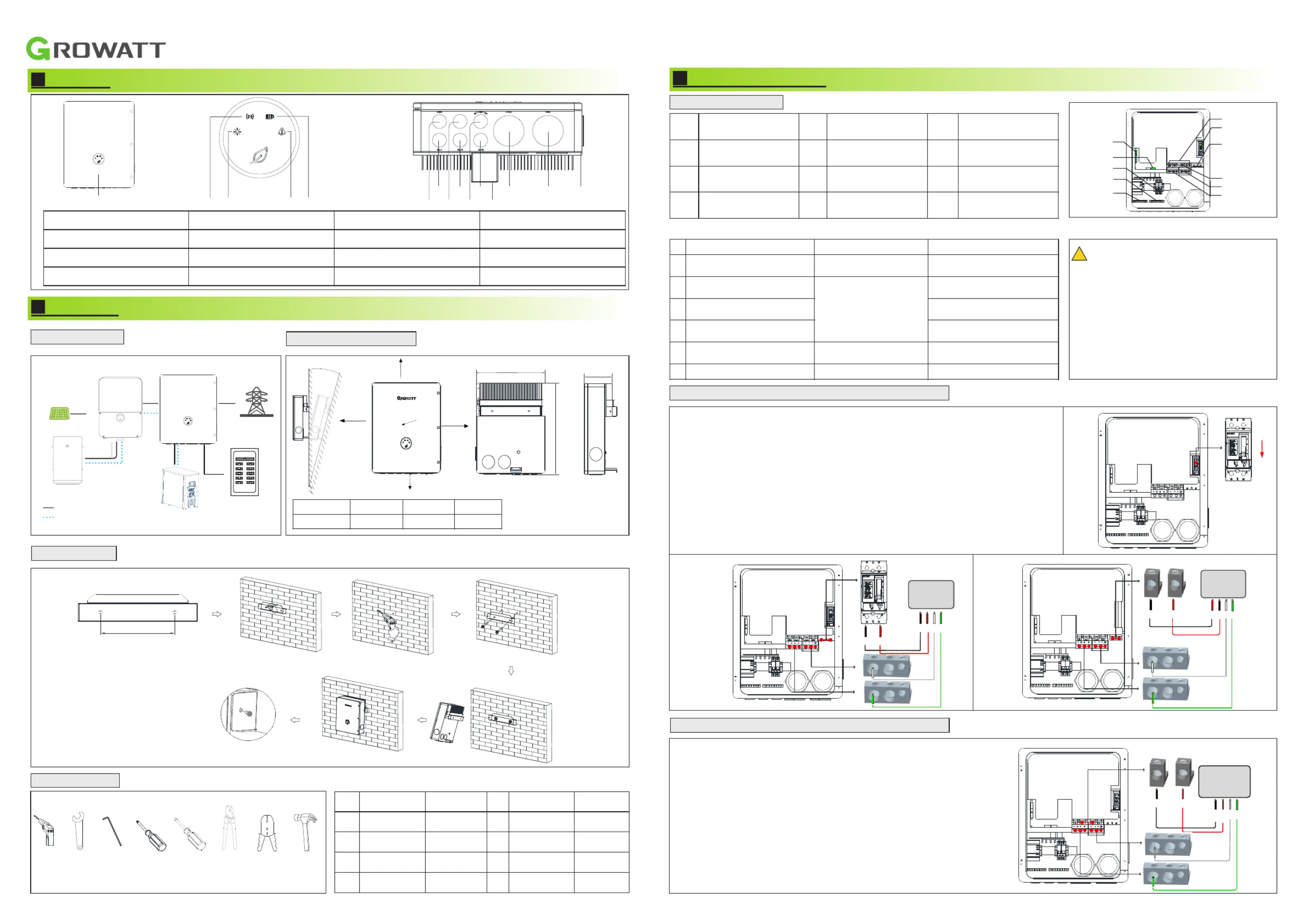
1Front panel:
2Grid indicator:
3Communication indicator:
4Status Indicator:
5Fault indicator:
6Inverter wiring port:
7Load wiring port:
8Grid wiring port:
9Heat sink:
10COM wiring port:
11 Reservedwiringport:
12Generator wiring port:
13Wall mount bracket:
No.
Name
Size
No.
Name
Size
1
Electric drill
Φ6mm
2
wrench
Φ10mm
3
Allen wrench
Φ5&6&8mm
4
Cross rise
Φ5mm
5
From flat
Φ1mm
6
Wire cutter
/
7
Wire stripper
/
8
hammer
/
3
3
3
33.
.
.
..
Electrical connection
3.1Electrical connection
24Required tools.
1236
78
32Connecting the SYN 200-XH-US to the Grid panel..
≤°15
≥300mm
≥300mm
≥500mm
≥300mm
≥300mm
Inverter
SYN 200-XH-US
Grid
Generator
Batery
PV
ON
A
B
C
DD
E
F
G
H
I
J
K
45
A
Inverter
communication port
B
Generatorcontrol
port
C
Inverter wiring port
D
Inverter Ground
Terminals
E
Inverter Neutral
Terminals
F
Generator wiring port
G
Grid switch
H
Grid wiring port
I
Load Panel wiring
prot
J
Main Neutral
Terminals
K
Main Ground
Terminals
Use
Type
Size
1
Grounding Conductors
(Load/Generator/Inverters)
Yellow-green jacketed or
solid bare copper
7~1/0 AWG(Load/Generator)
8~6 AWG(Inverters)
2
AC output conductors
(Load/Grid)
Multi-color jacket,
copper
0-4/0AWG
3
Generator Input
conductors
4~0 AWG
4
Inverter Input
conductors
6~5 AWG
5
12V power
output conductors
Red and black multi-
color copper
16~14 AWG
6
Communication cable
CAT5E suggested
/
Cables prepared by the customer:
!
Note:
It is recommended to use two or three
polychromatic multi-core copper cables cables
for Grid/Load/ Generator/ Inverter connection.
Recommended using yellow-green single
multi-core cables for PE connection.
Recommended using shielded twisted pair
cable for RS485 connection.
D
H
Grid_L1Grid_L2
Grid
N
PE
L1L2N
PE
W
LoadPanel
10111213
666789
1
OFF
ON
2
Grid
L1L2N
PE
L1
L2
3
Lad_L1o
Lad_L2o
L1L2N
PE
N
AC Loads Panel
PE
Powerwrie
Communication wrie
SYN200-XH-US447.5/17.62
DimsesionW(mm/inch)H(mm/inch)
555.5/21.87180.8/7.12
D(mm/inch)
240mm
33Connecting the SYN 200-XH-US to the Load panel..
1.Release the Allen screws of the upper cover and open the upper cover.
2. Install a conduit of the required diameter into the Grid conduit entry. Use the conduit
holder to support the conduit.
3. For versions with circuit breaker. Pull down the main breaker until it shows OFF.
Ensure that the main breaker is OFF, as shown in Figure 1.
4. Pass the cable from the grid through the grid conduit to the terminals of the circuit
breakerTighten the terminal screws with a torque of 230 in*lbs / 26N*m, as shown in .
Figure 2.
5. For version without circuit breaker. Pass the cable from the grid through the grid
conduit to the GridL1 and GridL2 terminals of the SYN 200-XH-USTighten the terminal .
screws with a torque of 221in*lbs / 25N*m, as shown in Figure 3.
6. Connect the neutral and grounding wires to the neutral and grounding terminals.
Tighten the terminal screws with a torque of 221in*lbs / 25N*m.
1.Install a conduit of the required diameter into the Loads conduit entry.
Use the conduit holder to support the conduit.
2. Pass the cable from the AC Loads panel through the Loads conduit to the
Load_L1 and Load_L2 terminals of the SYN 200-XH-US. Tighten the
terminal screws with a torque of 221in*lbs / 25N*m.
3. Connect the neutral and grounding wires to the neutral and grounding
terminals. Tighten the terminal screws with a torque of 221in*lbs / 25N*m,
as shown on the right.
Produktspezifikationen
| Marke: | Growatt |
| Kategorie: | Nicht kategorisiert |
| Modell: | SYN 200TL-XH-US |
Brauchst du Hilfe?
Wenn Sie Hilfe mit Growatt SYN 200TL-XH-US benötigen, stellen Sie unten eine Frage und andere Benutzer werden Ihnen antworten
Bedienungsanleitung Nicht kategorisiert Growatt

25 Februar 2026
23 Februar 2026
16 Februar 2026
16 Februar 2026
3 Februar 2026
3 Februar 2026
2 Februar 2026
2 Februar 2026
2 Februar 2026
13 Januar 2026
Bedienungsanleitung Nicht kategorisiert
Neueste Bedienungsanleitung für -Kategorien-
3 April 2026
3 April 2026
3 April 2026
3 April 2026
3 April 2026
3 April 2026
3 April 2026
3 April 2026
3 April 2026
3 April 2026