Hager HTG411H Bedienungsanleitung
Lies die bedienungsanleitung für Hager HTG411H (2 Seiten) kostenlos online; sie gehört zur Kategorie Schalter. Dieses Handbuch wurde von 3 Personen als hilfreich bewertet und erhielt im Schnitt 4.1 Sterne aus 9 Bewertungen. Hast du eine Frage zu Hager HTG411H oder möchtest du andere Nutzer dieses Produkts befragen? Stelle eine Frage
Seite 1/2
6LE007311B
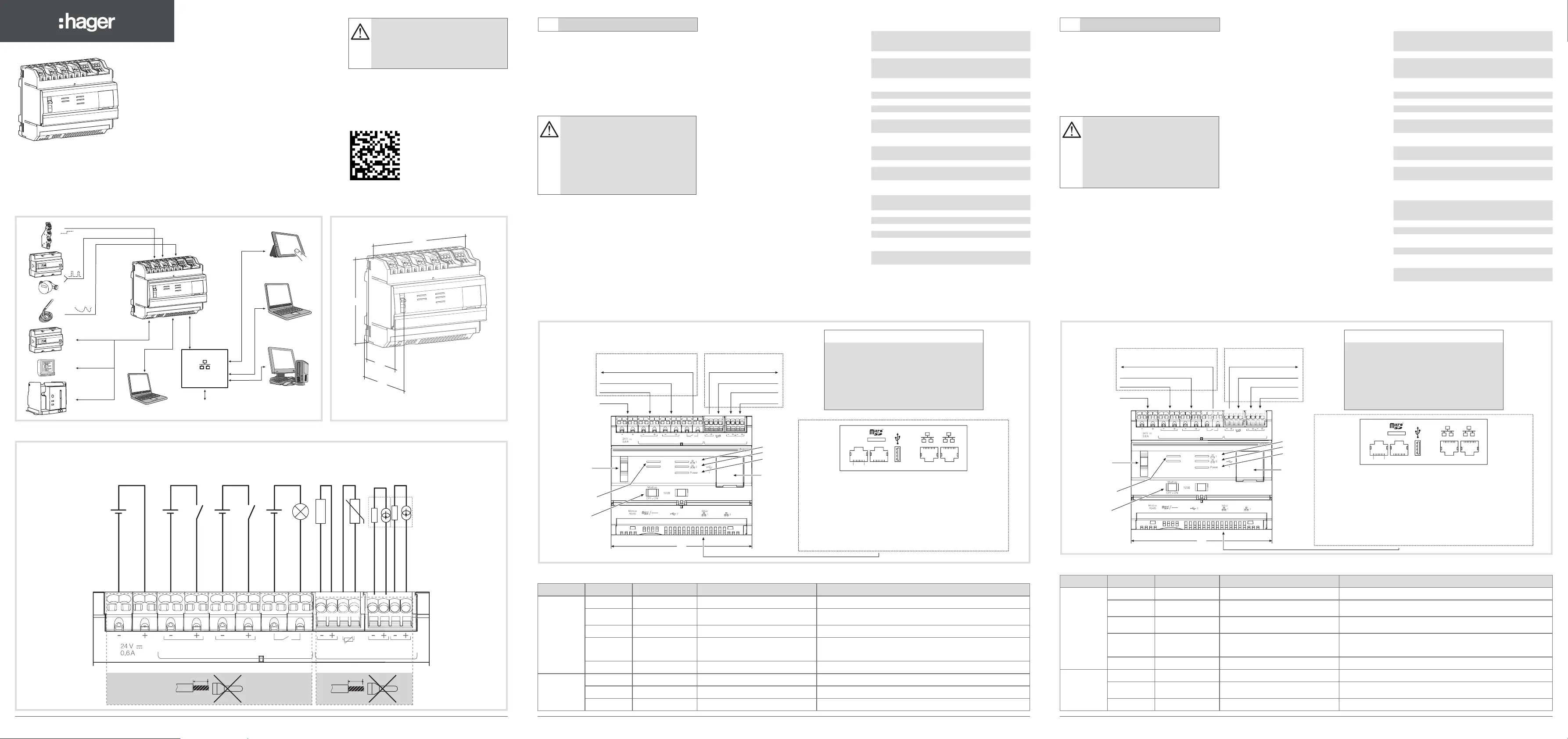
HTG410H / HTG411H - agardio.manager
z
Multi - energy data logger & server
a
Concentrateur et serveur
de données multi - énergies
e
Energiemonitoringserver
i
Multi - energie datalogger & server
Modbus RTU
Setup
T°
INTERNET
Router / Switch
HTG410H
107
90
67
60
4 - 20 mA input (-)
PT100 input
4 - 20 mA input (+)
0 - 10 V output (-)
0 - 10 V output (+)
Digital output
Digital output
Digital input 2 (-)
Digital input 2 (+)
Digital input 1 (-)
Digital input 1 (+)
24 V (-)
24 V s
TBTS, SELV
(+/- 10 %)
15 to 27 V s
TBTS, SELV
0,4VA
100 m max
Pulse > 30ms
15 to 27 V s
TBTS, SELV
0,4VA
100 m max
Pulse > 30ms
5 to 30 V s/v
TBTS, SELV
10 mA to 3 A
resistive
10 m max
T°
3 m max
Sensor
10 m max
>
_ 1 kΩ
10 m max
24 V (+)
4 - 20 mA input (-)
4 - 20 mA input (+)
10 mm
0,75 - 2,5 mm
2
8 mm
0,2 - 1,5 mm
2
Output
Digital
Analog
Output
Input 1Input 2
0-10
V4-20mA
Input
PT100
Input 1
Input 2
InterfaceDimensions / Dimensions / Abmessungen /
Afmetingen
Dimensions in mm / Dimensions en mm / Abmessungen in mm /
Afmetingen in mm
Connection / Raccordement / Anschluss / Aansluiting
Termination
resistor
120 Ω
Modbus RS485 (2)
6 0
HTG410H
ON
Setup
OFF
Modbus
Output
Digital
O
ut
p
u
t
Di
g
ita
l
Analog
Output
Input 1Input 2
0-10V4-20
mA
Input
PT100
Input 1
Input 2
6 0
1 Micro SD memory card slot
2 RJ45 port Modbus RS485
pin4: D1 or B/B' or "+" / green wire
pin5: D0 or A/A' or "-" / yellow wire
pin8: Common or C/C' or 0VL / brown wire
3 Not used
4 USB 2.0
5 RJ45 Setup port - Ethernet 1
6 RJ45 port - Ethernet 2
24 V s SELV
Digital input
Digital input
Output relay
DigitalAnalog
PT 100 input
4 - 20 mA input
4 - 20 mA input
0 - 10 V output
Important: The RS485 Modbus circuits must be connected only to external
RS485 Modbus circuits that are Safety Extra-Low Voltage (SELV).
Setup (1)
Selector
LED
Modbus
RS485
USB 2.0
LED
Ethernet 1
Ethernet 2
Power ON
2
1
2
2
Setup
1
3456
Modbus RS485
18
Front face and connections
LED information
LEDColourStateStatusSolution
Power
GreenFixedFunctional product./
Green
or orange
BlinkingProduct initialisation.
Wait for initialisation.
If the indication remains, refer to manual.
RedBlinkingProduct enters in power reserve.Wait during the shutdown progress.
Red or orangeFixedSoftware startup problem.
Perform a reset by switching the power supply off.
Wait for LED to switch off before switching the power supply on.
If the indication remains, refer to manual.
OffProduct not powered.Check the power supply.
Modbus
RS485 /
Ethernet 1 /
Ethernet 2
Green
Fixed / blinkingConnected and functional network./
OffNo communication network detected.Check the connection.
RedFixed / blinkingCommunication fault.Check the conguration of links.
The HTG410H is a multi-energy data logger
and server. The HTG411H version is delivered
additionally with a 4GB micro SD card. It is
intended to configure systems and products,
collect, store and time stamp information for
connected products. It processes this information
and monitors the quality of the electrical distribution
and makes it available to the user through an
embedded webserver. This product is accessible
from the Internet network.
Installation
The HTG410H / HTG411H must be tted on a DIN
rail.
Implementation
1. Connect the inputs / outputs on the HTG410H /
HTG411H terminal block.
2. Connect the Modbus and Ethernet networks as
appropriate.
3. Enable 120 Ω termination resistor (selector (2) to
set to «ON») if the product is tted at the end of the
Modbus network.
4. Check that the selector «Setup» (1) is in «OFF»
position.
5. Connect the 24 V s power supply (SELV).
First conguration
1. Start the software update:
a) download the latest software version from http://
hgr.io/r/htg410h or http://hgr.io/r/htg411h
b) unzip the downloaded le
c) read the le «readme.txt»
2. Connect the computer to the RJ45
«Setup - Ehernet 1» connector of HTG410H /
HTG411H using the Ethernet cable.
3. Turn switch «Setup» (1) in «ON» position.
4. Perform a reset by switching the power
supply off and again on.
5. Activate the Web browser on the computer.
6. Enter: url : https://192.168.0.1
login : admin
password : admin
7. Setting the HTG410H / HTG411H, refer to the user
guide, downloadable from http://hgr.io/r/htg410h
or http://hgr.io/r/htg411h website or with the
Datamatrix scanning.
The energy server has two operating modes:
- Stand-alone mode : The server is still the
master component in the installation and obtains
measurements from connected meters.
- Supervised mode: The server is used as a
gateway to send data to the Energy Management
System stream. Several functions in the menus are
inaccessible in this mode (see user manual).
Switch to supervised mode
1. Go to the Preferences menu.
2. Select the System tab.
3. In the Supervised mode section, check yes to
enable the mode.
4. Click on Save.
When the energy server is rebooted, it restarts in
supervised mode.
*: The use of product at the maximal temperature can reduce its life expectancy.
Prerequisite for installation:
Equipment:
- a computer with internet browser
(Chrome recommended),
- an RJ45 Ethernet cable.
In case of an extended Ethernet network:
- an Ethernet network socket,
- product name on the network,
- a static or dynamic IP address,
- the network mask.
z Operating manuel via internet
a Manuel utilisateur via internet
e Bedienungsanleitung via internet
iInstallatiehandleiding en
gebruikershandleiding via internet
This device is to be installed only by a
professional electrician tter according to
local applicable installation standards.
Do not install this module outside the
building.
Power supply over Ethernet (PoE)
prohibited.
In "Setup ON" mode, the HTG410H
activates its DHCP server on "Setup -
Ethernet 1" port.
6LE007311B16LE007311B2
Z
Z
http://hgr.io/r/htg410h
http://hgr.io/r/htg411h
Technical characteristics
External safety extra low
voltage power supply
24 V
s
(SELV)
+/- 10 %
Typical consumption
7 VA
Ethernet network
com munication
Ethernet - TCP / IP -
RJ45 / 100 base - T /
IEEE 802.3
Modbus network
com munication
RS485 Modbus RJ45
Operating temperature
-25° to +70°C*
Storage temperature
-55° to +85°C
Humidity storage
95% max HR at 55°C
Binary digital input 1 and 2
15 to 27 V
s
Analog input
4 - 20 mA
1 and 2
Input impedance
<300 Ohms
PT 100 input
2-wire probe -
EN 60751 compliance
Binary digital output
5 to 30 V
s
/
v
10 mA to 3 A
resistive dry contact
Number of relay cycles
100000
Analog output
0 - 10 VMin impedance
>= 1 kOhms
Power supply, digital inputs,
digital output connection
0.75 - 2.5 mm²
Analog inputs, analog
output connection
0.2 - 1.5 mm²
Degree of protection
IP 20
Weight
290 g
Maximum operating altitude
2 000 m
Micro SD card
Class 10
USB port 1
(front face)
USB 2.0 Type A
standard connector
USB port 2
(under the product)
USB 2.0 Type A
standard connector
6 0
Output
Digital
O
ut
p
u
t
Digita
l
Analog
Output
Input 1Input 2
0-10V4-20
mA
Input
PT100
Input 1
Input 2
HTG410H
ON
Setup
OFF
Modbus
Sélecteur (1)
Setup
Led
Modbus
RS485
USB 2.0
Résistance
de terminaison
120 Ω
Modbus RS485 (2)
Led
Ethernet 1
Ethernet 2
Power
1 Logement pour carte mémoire Micro SD
2 Port RJ45 Modbus RS485
broche4 : D1 ou B/B' ou "+" / conducteur vert
broche5 : D0 ou A/A' ou "-" / conducteur jaune
broche8 : Commun ou C/C' ou 0VL / conducteur marron
3 Non utilisé
4 USB 2.0
5 Port RJ45 Setup - Ethernet 1
6 Port RJ45 - Ethernet 2
24 V s TBTS, SELV
Entrée TOR
Entrée TOR
Sortie relais
DigitaleAnalogique
Entrée PT 100
Entrée 4 - 20 mA
Entrée 4 - 20 mA
Sortie 0 - 10 V
Important : Le réseau RS485 Modbus ne doit être uniquement raccordé à un réseau
RS485 Modbus externe qui soit Très Basse Tension de Sécurité (TBTS - SELV).
2
1
2
2
Setup
1
3456
Modbus RS485
18
Face avant et connections
Fonctionnement des LED
LedCouleurEtatSignicationCorrection du défaut
Power
VertFixeProduit fonctionnel./
Vert
ou orange
ClignotantInitialisation du produit.
Attendre la n de l’initialisation.
Si l’indication persiste, consulter la notice.
RougeClignotant
Le produit entre dans la réserve de
marche.
Attendez pendant la progression de l'arrêt.
Rouge
ou orange
FixeProblème de démarrage du logiciel.
Effectuer une réinitialisation en coupant l’alimentation.
Attendre l’extinction des Led avant de remettre le produit
sous tension. Si l’indication persiste, consulter la notice.
EteinteProduit non alimenté.Vérier l’alimentation électrique.
Modbus
RS485 /
Ethernet 1 /
Ethernet 2
VertFixe / clignotantRéseau raccordé et fonctionnel./
Eteinte
Aucun réseau de communication
détecté.
Vérier le raccordement.
RougeFixe / clignotantDéfaut de communication.Vérier la conguration des liaisons.
Le HTG410H est un concentrateur et serveur de
données multi-énergies. La version HTG411H est
livrée en plus avec une carte micro SD de 4 Go.
Il est destiné à configurer système et produits,
relever, stocker et horodater les informations des
produits connectés. Il traite ces informations et
surveille la qualité de la distribution électrique. Il
les met à disposition de l’utilisateur au travers d’un
webserveur embarqué. Ce produit peut être rendu
accessible depuis le réseau Internet.
Installation
Le HTG410H / HTG411H se clipse directement sur un
rail DIN.
Mise en œuvre
1. Raccorder les entrées / sorties sur le bornier du
HTG410H / HTG411H.
2. Connecter les réseaux Modbus et Ethernet le cas
échéant.
3. Activer la résistance de terminaison 120 Ω
(sélecteur (2) à mettre sur "ON") si le produit est en
extrémité de réseau Modbus.
4. Vérier que le sélecteur "Setup" (1) soit en position
"OFF".
5. Connecter l’alimentation 24 V s (TBTS, SELV).
Première conguration
1. Lancer la mise à jour du logiciel :
a) télécharger la dernière version du logiciel à partir
de http://hgr.io/r/htg410h ou http://hgr.io/r/htg411h
b) décompresser le chier téléchargé
c) lire le chier «readme.txt»
2. Connecter l’ordinateur au port "Setup - Ehernet
1" du HTG410H / HTG411H à l’aide du câble
Ethernet.
3. Mettre le sélecteur "Setup" (1) en position "ON".
4. Couper l’alimentation, puis remettre le produit sous
tension.
5. Lancer le navigateur internet sur l’ordinateur.
6. Saisir : url : https://192.168.0.1
login : admin
password : admin
7. Paramétrage du HTG410H / HTG411H, se reporter
à la notice d’utilisation, téléchargeable sur le site
internet http://hgr.io/r/htg410h ou http://hgr.io/r/
htg411h ou en ashant le Datamatrix.
Le serveur énergétique dispose de 2 modes de
fonctionnement :
- Le mode standalone : Le serveur reste maître
dans l'installation et relève les mesures à partir des
compteurs reliés.
- Le mode supervisé : Le serveur est utilisé en tant
que passerelle pour transmettre les données vers
l'Energy Management System stream. Plusieurs
fonctions dans les menus sont alors inaccessible (voir
manuel d'utilisation).
Basculement en mode supervisé
1. Allez dans le menu Préférences.
2. Sélectionnez l'onglet Système.
3. Dans la section Mode supervisé, cochez oui pour
activer le mode.
4. Cliquez sur Sauvegarder.
Au prochain reboot, le serveur énergétique redémarre
en mode supervisé.
*: L'utilisation du produit à la température maximale peut réduire sa durée de vie.
Pré-requis pour l’installation :
Matériel :
- Un ordinateur avec navigateur internet
(Chrome recommandé),
- Un câble Ethernet RJ45.
Dans le cas d’un réseau Ethernet étendu :
- une prise réseau Ethernet,
- le nom du produit sur le réseau,
- une adresse IP statique ou dynamique,
- le masque du réseau.
Appareil à installer uniquement par un
installateur électricien selon les normes
d’installation en vigueur dans le pays.
Ne pas installer ce module à l’extérieur
du bâtiment.
Alimentation via Ethernet (PoE) interdit.
En mode "Setup ON", le HTG410H active
son serveur DHCP sur le port "Setup -
Ethernet 1".
6LE007311B3
A
A
Caractéristiques techniques
Alimentation très basse
tension de sécurité externe
24 V
s
(TBTS, SELV)
+/- 10 %
Consommation typique
7 VA
Communication réseau
Ethernet
Ethernet - TCP / IP -
RJ100 / 45base - T /
IEEE 802.3
Communication réseau
Modbus
RS485 Modbus RJ45
T° de fonctionnement
°25- à °70+C*
T° de stockage
°55- à °85+C
Humidité stockage
%95 max HR à °55C
Entrée digitale TOR 1 et 2
15 à 27 V
s
Entrée analogique
4 - 20 mA
1 et 2
Impédance d'entrée
<300 Ohms
Entrée PT 100
Sonde 2 fils -
Compatible EN 60751
Sortie digitale TOR
5 à 30 V
s
/
v
10 mA à 3 A
resistif contact sec
Nombre de cycles du relais
100000
Sortie analogique
0 - 10 VImpédance mini
>= 1 kOhms
Raccordement alimentation,
entrées digitales, sortie
digitale.
2,5 - 0,75 mm²
Raccordement entrées
analogiques, sortie
analogique
1,5 - 0,2 mm²
Indice de protection
IP 20
Masse
290 g
Altitude maximale
d'utilisation
2000 m
Carte micro SD
Classe 10
Port USB 1
(en façade)
USB 2.0 Type A
connecteur standard
Port USB 2
(sous le produit)
USB 2.0 Type A
connecteur standard
Produktspezifikationen
| Marke: | Hager |
| Kategorie: | Schalter |
| Modell: | HTG411H |
Brauchst du Hilfe?
Wenn Sie Hilfe mit Hager HTG411H benötigen, stellen Sie unten eine Frage und andere Benutzer werden Ihnen antworten
Bedienungsanleitung Schalter Hager

9 Oktober 2025
26 September 2025
26 September 2025
26 September 2025
26 September 2025
26 September 2025
26 September 2025
26 September 2025
26 September 2025
26 September 2025
Bedienungsanleitung Schalter
Neueste Bedienungsanleitung für -Kategorien-
31 März 2026
30 März 2026
25 März 2026
22 März 2026
22 März 2026
21 März 2026
20 März 2026
20 März 2026
19 März 2026
19 März 2026