Hikvision DS-K5671-ZV Bedienungsanleitung
Hikvision Sicherheitszugangskontrollsystem DS-K5671-ZV
Lies die bedienungsanleitung für Hikvision DS-K5671-ZV (2 Seiten) kostenlos online; sie gehört zur Kategorie Sicherheitszugangskontrollsystem. Dieses Handbuch wurde von 10 Personen als hilfreich bewertet und erhielt im Schnitt 4.3 Sterne aus 7 Bewertungen. Hast du eine Frage zu Hikvision DS-K5671-ZV oder möchtest du andere Nutzer dieses Produkts befragen? Stelle eine Frage
Seite 1/2
DS-K5671 Series Face Recognition Terminal
Quick Start Guide
©2020 Hangzhou Hikvision Digital Technology Co., Ltd. All rights reserved.
About this Manual
The Manual includes instrucons for using and managing the Product. Pictures, charts, images
and all other informaon hereinaer are for descripon and explanaon only. The informaon
contained in the Manual is subject to change, without noce, due to firmware updates or other
reasons. Please find the latest version of this Manual at the Hikvision website
(hps://www.hikvision.com/).
Please use this Manual with the guidance and assistance of professionals trained in supporng
the Product.
Trademarks
and other Hikvision's trademarks and logos are the properes of Hikvision in various
jurisdicons.
Other trademarks and logos menoned are the properes of their respecve owners.
Disclaimer
TO THE MAXIMUM EXTENT PERMITTED BY APPLICABLE LAW, THIS MANUAL AND THE PRODUCT
DESCRIBED, WITH ITS HARDWARE, SOFTWARE AND FIRMWARE, ARE PROVIDED “AS IS” AND
“WITH ALL FAULTS AND ERRORS”. HIKVISION MAKES NO WARRANTIES, EXPRESS OR IMPLIED,
INCLUDING WITHOUT LIMITATION, MERCHANTABILITY, SATISFACTORY QUALITY, OR FITNESS
FOR A PARTICULAR PURPOSE. THE USE OF THE PRODUCT BY YOU IS AT YOUR OWN RISK. IN NO
EVENT WILL HIKVISION BE LIABLE TO YOU FOR ANY SPECIAL, CONSEQUENTIAL, INCIDENTAL, OR
INDIRECT DAMAGES, INCLUDING, AMONG OTHERS, DAMAGES FOR LOSS OF BUSINESS PROFITS,
BUSINESS INTERRUPTION, OR LOSS OF DATA, CORRUPTION OF SYSTEMS, OR LOSS OF
DOCUMENTATION, WHETHER BASED ON BREACH OF CONTRACT, TORT (INCLUDING
NEGLIGENCE), PRODUCT LIABILITY, OR OTHERWISE, IN CONNECTION WITH THE USE OF THE
PRODUCT, EVEN IF HIKVISION HAS BEEN ADVISED OF THE POSSIBILITY OF SUCH DAMAGES OR
LOSS.
YOU ACKNOWLEDGE THAT THE NATURE OF INTERNET PROVIDES FOR INHERENT SECURITY
RISKS, AND HIKVISION SHALL NOT TAKE ANY RESPONSIBILITIES FOR ABNORMAL OPERATION,
PRIVACY LEAKAGE OR OTHER DAMAGES RESULTING FROM CYBER-ATTACK, HACKER ATTACK,
VIRUS INFECTION, OR OTHER INTERNET SECURITY RISKS; HOWEVER, HIKVISION WILL PROVIDE
TIMELY TECHNICAL SUPPORT IF REQUIRED.
YOU AGREE TO USE THIS PRODUCT IN COMPLIANCE WITH ALL APPLICABLE LAWS, AND YOU ARE
SOLELY RESPONSIBLE FOR ENSURING THAT YOUR USE CONFORMS TO THE APPLICABLE LAW.
ESPECIALLY, YOU ARE RESPONSIBLE, FOR USING THIS PRODUCT IN A MANNER THAT DOES NOT
INFRINGE ON THE RIGHTS OF THIRD PARTIES, INCLUDING WITHOUT LIMITATION, RIGHTS OF
PUBLICITY, INTELLECTUAL PROPERTY RIGHTS, OR DATA PROTECTION AND OTHER PRIVACY
RIGHTS. YOU SHALL NOT USE THIS PRODUCT FOR ANY PROHIBITED END-USES, INCLUDING THE
DEVELOPMENT OR PRODUCTION OF WEAPONS OF MASS DESTRUCTION, THE DEVELOPMENT OR
PRODUCTION OF CHEMICAL OR BIOLOGICAL WEAPONS, ANY ACTIVITIES IN THE CONTEXT
RELATED TO ANY NUCLEAR EXPLOSIVE OR UNSAFE NUCLEAR FUEL-CYCLE, OR IN SUPPORT OF
HUMAN RIGHTS ABUSES.
IN THE EVENT OF ANY CONFLICTS BETWEEN THIS MANUAL AND THE APPLICABLE LAW, THE
LATER PREVAILS.
Data Protecon
During the use of device, personal data will be collected, stored and processed. To protect data,
the development of Hikvision devices incorporates privacy by design principles. For example,
for device with facial recognion features, biometrics data is stored in your device with
encrypon method; for fingerprint device, only fingerprint template will be saved, which is
impossible to reconstruct a fingerprint image.
As data controller, you are advised to collect, store, process and transfer data in accordance
with the applicable data protecon laws and regulaons, including without limitaon,
conducng security controls to safeguard personal data, such as, implemenng reasonable
administrave and physical security controls, conduct periodic reviews and assessments of the
effecveness of your security controls.
Scan the QR code to get the user manual for detailed informaon.
UD15611B-C
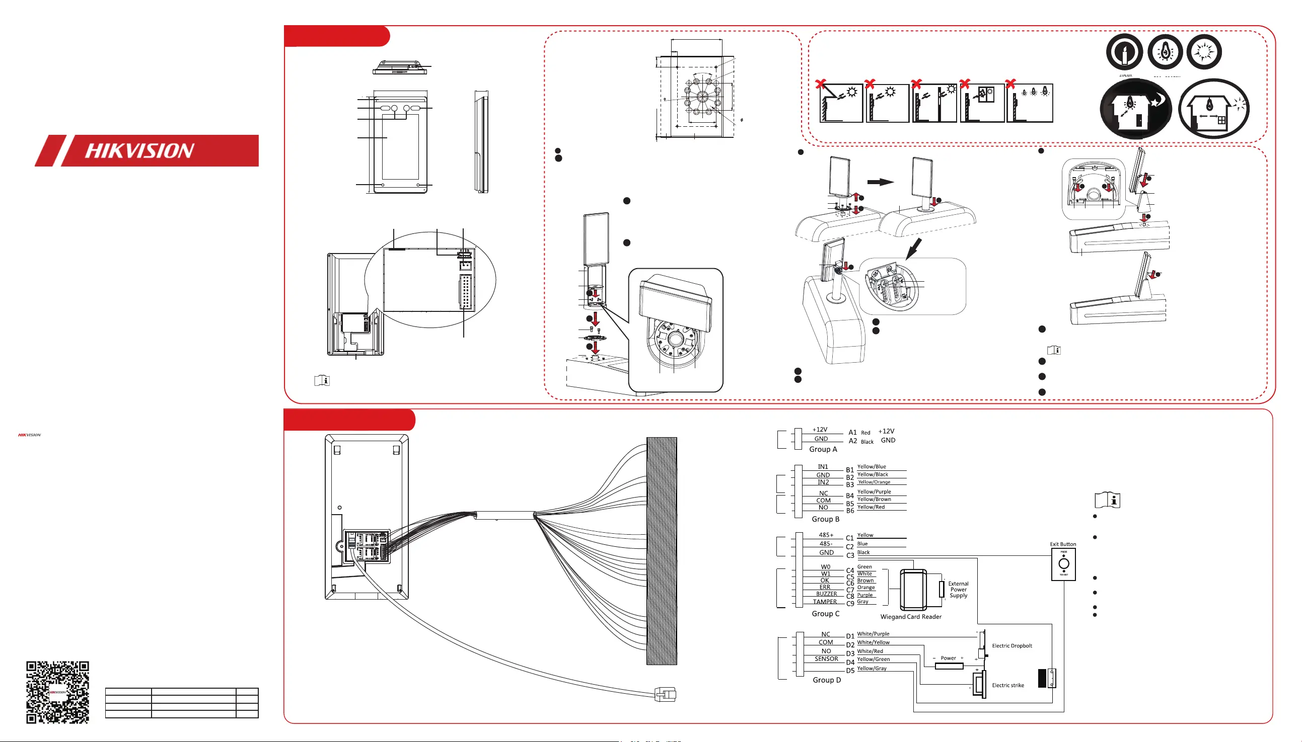
2.1 Wiring (Normal)
When connecng door contact and exit buon,
the device and the RS-485 card reader should
use the same common ground connecon.
The Wiegand terminal here is a Wiegand input
terminal. You should set the device’s Wiegand
direcon to “input”. If you should connect to
an access controller, you should set the
Wiegand direcon to “Output”. For details, see
the user manual.
The suggested external power supply for door
lock is 12 V, 1 A.
Thesuggestedexternal power supply for
Wiegand card reader is 12 V, 1 A.
Forwiringthefiresystem, see the user manul.
Do not wire the device to the electric supply
directly.
1 Installation
The figures are for reference only.
BacklightDirect
Sunlight
Direct Sunlight
through Window
Indirect Sunlight
through Window
Close to Light
Installaon Environment:
Indoor and outdoor installaon are supported. if installing the device indoors, the device
should be at least 2 meters away from the light, and at least 3 meters away from the
window or the door. If installing the device outdoors, you should apply Silicone sealant
among the cable wiring area to keep the raindrop from entering.
Use only power supplies listed in the user instrucons:
ModelManufacturerStandard
C2000IC12.0-24P-DE
C2000IC12.0-24P-GB
ADS-24S-12 1224GPG
MOSO Power Supply Technology Co., Ltd
MOSO Power Supply Technology Co., Ltd
Shenzhen Honor Electronic Co., Ltd
CEE
CEE
BS
BTN
Power Input
Alarm Input
Alarm Output
RS-485
Wiegand
Door Lock
Network Interface
126.6 mm
228.6 mm
31.55 mm
Appearance:
White Light
IR Light
Camera
Screen
Infrared
Intrusion
Detector
Infrared
Intrusion
Detector
White
Light
USB Interface
Network
Interface
Debugging
Port
Power
Interface
Wiring
Terminal
Indicator
10Lux
>1200Lux100~850Lux
3m
2m
1
2
1
2
3
3
1
2
3
3
4
4
2
1
2
67 mm
67 mm
80 mm
Align the hole on the turnsle and place the base on the turnsle. Rotate
the base to the acquired place to make sure the device will face a correct
direcon. Then secure the base with 2 screws.
1. The arrow indicaon on the base and the turnsle should be approximately vercal.
2. Refer to the scales and scale arrow on the base to confirm the screws’ posion.
The screws’ posion indicated scale is the rotate angle of the device.
Route the cables through the cable hole on the
turnsle and place the device with bracket on the
base and make sure the arrow on the base is
aligned with the arrow shaped slot on the bracket.
In this case, the holes on the bracket is aligned with
those on the base.
Align the arrow indicaon on the base with that
inside the upper cover and place the upper cover in
the lower cover. Rotate the upper cover to the right
unl the buckle is fastened.
3
1. Use 4 screws (M3 or M4),
secured by flange nuts, to
install the reinforcing board
on the inner surface of the
turnsle.
Note: The distance between the
turnsle and the edge should be
no longer than 10 mm.
2. Drill holes on the
turnsle’s inner surface
according to the figure
displayed below. And install
water-proof nut.
Note: Solder aer pressing rivets
to avoid water from entering.
Mounng with Bracket
Before you start:
Width of Reinforcing Board > 125 mm
15 mm(Suggested)
Use 4 screws (M3 or M4),
Secured by flange nuts
Press 8 rivet water-proof
nut
Model: BS-M6-1
4- 12mm Soldering Hole
Solder the four holes,
polish the outer surface,
and implement with wire
drawing.
Reinforcing Board
Inner Surface
of Turnsitle
15 mm(Suggested)
The distance between the turnsle
and the board edge should be no longer
than 10 mm.
Device
with Bracket
Upper
Cover
Lower Cover
Installaon
Screws
Installaon
Screws
Base
Turnsle
Screw HoleArrow Shaped Slot
Top View
Arrow Indicaon
Cover the lower cover on the base and rotate to secure.
Loosen the screws inside and adjust the device elevaon. Aer adjustment,
secure the screws and install the upper cover.
The default elevaon angle is 15°. Theadjustable elevaon angle is from 0 to 15°.
Rotate to open the lower cover.
Route the cables through the cable hole on the
turnsle.
Align the holes on the base with those on the
turnsle and place the device with bracket on the
turnsle. Use 4 screws to secure the bracket and
the turnsle.
4
2
1
Lower Cover
Screw
Base
Upper Cover
Turnsle
Screws for
Elevaon
Adjustment
Bracket Type III
Bracket Type I
Bracket Type II
Screw
Mounng Plate
Sheet
Bracket
Turnsle
ScrewScrewSlotSlot
Route the cables through the cable hole on the turnsle. Align the holes on
the bracket and those on the turnsle and place the bracket on the
turnsle.
You can replace the decoraon sheet by the arch shaped decoraon for some
circumstance. For details, see the user manual.
Rotate to adjust the bracket’s angle and secure the bracket on the turnsle
with 2 screws.
Align the device with bracket and slide the device in the bracket. Make sure
the two sheets of the mounng plate are in the slots.
Secure the device and the bracket with a screw.
1
2
3
4
GND
(NC)
(COM)
(NO)
Door Contact
Produktspezifikationen
| Marke: | Hikvision |
| Kategorie: | Sicherheitszugangskontrollsystem |
| Modell: | DS-K5671-ZV |
Brauchst du Hilfe?
Wenn Sie Hilfe mit Hikvision DS-K5671-ZV benötigen, stellen Sie unten eine Frage und andere Benutzer werden Ihnen antworten
Bedienungsanleitung Sicherheitszugangskontrollsystem Hikvision

29 März 2026
11 März 2026
10 März 2026
2 November 2025
1 November 2025
1 November 2025
1 November 2025
31 Oktober 2025
31 Oktober 2025
9 Oktober 2025
Bedienungsanleitung Sicherheitszugangskontrollsystem
Neueste Bedienungsanleitung für -Kategorien-
26 März 2026
22 März 2026
20 März 2026
4 Januar 2026
31 Dezember 2026
29 Dezember 2026
21 November 2025
14 November 2025
2 November 2025
1 November 2025