IFM AL1020 Bedienungsanleitung
IFM Nicht kategorisiert AL1020
Lies die bedienungsanleitung für IFM AL1020 (2 Seiten) kostenlos online; sie gehört zur Kategorie Nicht kategorisiert. Dieses Handbuch wurde von 17 Personen als hilfreich bewertet und erhielt im Schnitt 4.1 Sterne aus 3 Bewertungen. Hast du eine Frage zu IFM AL1020 oder möchtest du andere Nutzer dieses Produkts befragen? Stelle eine Frage
Seite 1/2
ESPAÑOL
ifm electronic gmbh
Friedrichstraße 1
45128 Essen
MNR 9068671 - 02
www.ifm.com
Dispositivi di input ed output IO-Link per
EtherNet, custodia in plastica
1.Indicazioni di sicurezza
2.Nota per il montaggio
–Mettere a terra il dispositivo mediante le viti di fissaggio.
–Garantire il grado di protezione IP 67! Verificare la tenuta delle
alimentazioni dei cavi; utilizzare cappucci di sicurezza per le
connessioni non utilizzate oppure cavi con estremità munite di
guarnizioni di gomma.
3.Montaggio del dispositivo in plastica ()
Avvitare il dispositivo in prossimità delle linguette di fissaggio
direttamente su una superficie di montaggio piana.
4.Collegare i conduttori ()
Connettere i cavi per il bus, le alimentazioni di tensione e le porte.
Se si desidera impiegare in parallelo entrambe le funzioni delle
porte, utilizzare un distributore a Y.
5.Collegamenti sul dispositivo ()
6.Assegnazione pin EtherNet ()
7.Assegnamento dei pin PWR ()
8.Assegnazione dei pin delle porte ()
IMPORTANTE:
Nel maneggiare elementi a rischio di scariche
elettrostatiche, osservare le necessarie misure di
sicurezza (EN61340-5-1 e IEC61340-5-1)!
IMPORTANTE: Sono possibili danni all'elettronica in
caso di sovraccarico
Il dispositivo è concepito per una tensione di 24VDC. Non
far funzionare il dispositivo con tensioni superiori.
Rispettare scrupolosamente anche le informazioni fornite
nella scheda tecnica e nel manuale utente.
CollegamentoSignificato
1FETerra funzionale
2Porta 1 (X21)Porta EtherNet 1
3Porta 2 (X22)Porta EtherNet 2
4PWR IN (X31)Alimentazione di tensione IN
(tensione di alimentazione UL e porte
IO-Link e ingressi digitali)
5PWR OUT (X32)Alimentazione di tensione OUT
(tensione di alimentazione UL e porte
IO-Link per altri dispositivi)
6IO-Link-A-Ports
(X01 ... X04)
IO-Link-A-Ports 1 ... 4
7IN (X01 ... X04)Ingressi digitali 1 ... 4
8IO-Link-B-Ports
(X05 ... X08)
Porte IO-Link-B 1... 4
PinPorta EtherNet 1 (X21)Porta EtherNet 2 (X22)
1TX+TX+
2RX+RX+
3TX-TX-
4RX-RX-
PinPWR IN (X31)PWR IN (X32)Colori dei
conduttori
1+24 V DC (U
S
)+24 V DC (U
S
)Marrone
2GND (U
A
)GND (U
A
)Bianco
3GND (U
S
)GND (U
S
)Blu
4+24 V DC (U
A
)+24 V DC (U
A
)Nero
PinIO-Link-A-Ports
(X01 ... X04)
IO-Link-B-Ports
(X05 ... X08)
124 V DC (L+)24 V DC (L+)
2DI24 V DC (U
A
)
3GND (L-)GND (L-)
4C/QC/Q
5liberoGND (U
A
)
Appareils d'entrée et de sortie IO-Link pour
EtherNet, boîtier plastique
1.Consignes de sécurité
2.Instructions de montage
–Mettre l'appareil à la terre au moyen des vis de fixation.
–S'assurer que l'indice de protection IP67 est garanti. Veiller à
ce que les arrivées de câble soient étanches et employer des
bouchons de protection pour les connexions inutilisées ou les
extrémités de câbles pourvues de joints en caoutchouc.
3.Montage de l'appareil à boîtier plastique ()
Visser solidement l'appareil sur les colliers de fixations
directement sur une surface de montage plane.
4.Raccordement des câbles ()
Raccorder les câbles destinés au bus, les alimentations en
tension et les ports.
Si vous souhaitez utiliser les deux fonctions du port (IO-Link / DI)
en parallèle, utilisez un répartiteur en Y.
5.Connexions sur l'appareil ()
6.Affectation des broches EtherNet ()
7.Affectation des broches PWR ()
8.Affectation des broches du port ()
IMPORTANT:
Observer les mesures de précaution nécessaires lors du
maniement des composants sensibles aux décharges
électrostatiques (EN61340-5-1, CEI61340-5-1).
IMPORTANT : dommages électroniques en cas de
surcharge
L'appareil est conçu pour une tension de 24VDC. Ne
jamais exploiter l'appareil avec une tension supérieure.
Observer également les autres informations de la fiche
technique correspondante et du manuel d'utilisation.
RaccordementSignification
1FETerre de fonctionnement
2Port 1 (X21)Port EtherNet 1
3Port 2 (X22)Port EtherNet 2
4PWR IN (X31)Alimentation en tension IN (tension
logique et ports IO-Link et entrées
TOR)
5PWR OUT (X32)Alimentation en tension OUT
(tension logique et ports IO-Link pour
d'autres appareils)
6IO-Link-A-Ports
(X01 ... X04)
IO-Link-A-Ports 1 ... 4
7IN (X01 ... X04)Entrées TOR 1 ... 4
8IO-Link-B-Ports
(X05 ... X08)
Ports B IO-Link 1... 4
BrochePort EtherNet 1 (X21)Port EtherNet 2 (X22)
1TX+TX+
2RX+RX+
3TX-TX-
4RX-RX-
BrochePWR IN (X31)PWR IN (X32)Couleurs des
fils
1+24 V DC (U
S
)+24 V DC (U
S
)Marron
2GND (U
A
)GND (U
A
)Blanc
3GND U
S
GND U
S
Bleu
4+24 V DC (U
A
)+24 V DC (U
A
)Noir
BrocheIO-Link-A-Ports
(X01 ... X04)
IO-Link-B-Ports
(X05 ... X08)
124 V DC (L+)24 V DC (L+)
2DI24 V DC (U
A
)
3GND (L-)GND (L-)
4C/QC/Q
5Non équipéGND (U
A
)
U
S
:18 V DC ... 31,2 V DC
(180 mA ± 15 % pour 24 V DC)
U
A
:18 V DC ... 31,2 V DC
(28 mA ± 15 % pour 24 V DC)
Outputs:18 V DC ... 31,2 V DC
(8 x 200 mA /max. 1,6 A)
Température ambiante:-25°C≤T
amb
≤+60°C
IO-Link input and output devices for
EtherNet, plastic housing
1.Safety notes
2.Installation instructions
–Ground the device by means of the mounting screws.
–Ensure IP67 degree of protection. Pay attention to the sealing
of the cable feed-through and use protective caps for
connections not used or cable ends with rubber seals.
3.Mounting the plastic device ()
Screw the module tightly down onto a flat surface using the fixing
clips.
4.Connecting cables ()
Connect the cables for the bus, voltage supplies and the ports.
If you wish to use both port functions (IO-Link/DI) in parallel,
install a Y distributor.
5.Connections on the device ()
6.EtherNet pin assignment ()
7.PWR pin assignment ()
8.Pin assignment of the ports ()
NOTE:
Observe the necessary safety precautions when handling
components that are vulnerable to electrostatic discharge
(EN61340-5-1 and IEC61340-5-1)!
NOTE: Electronics may be damaged when
overloaded
The device is designed for a voltage of 24VDC. Do not
operate the device at higher voltages.
Strictly observe the additional information in the data sheet
and the user manual.
ConnectionMeaning
1FEFunctional earth ground
2Port 1 (X21)EtherNet port 1
3Port 2 (X22)EtherNet port 2
4PWR IN (X31)Power supply IN (communications
power and IO-Link ports and digital
inputs)
5PWR OUT (X32)Power supply OUT (communications
power and IO link ports for additional
devices)
6IO-Link-A-Ports
(X01 ... X04)
IO-Link-A-Ports 1 ... 4
7IN (X01 ... X04)Digital inputs 1 ... 4
8IO-Link-B-Ports
(X05 ... X08)
IO-Link B ports 1... 4
PinEtherNet port 1 (X21)EtherNet port 2 (X22)
1TX+TX+
2RX+RX+
3TX-TX-
4RX-RX-
PinPWR IN (X31)PWR IN (X32)Conductor
colors
1+24 V DC (U
S
)+24 V DC (U
S
)Brown
2GND (U
A
)GND (U
A
)White
3GND (U
S
)GND (U
S
)Blue
4+24 V DC (U
A
)+24 V DC (U
A
)Black
PinIO-Link-A-Ports
(X01 ... X04)
IO-Link-B-Ports
(X05 ... X08)
124 V DC (L+)24 V DC (L+)
2DI24 V DC (U
A
)
3GND (L-)GND (L-)
4C/QC/Q
5Not usedGND (U
A
)
U
S
:18 V DC ... 31.2 V DC
(180 mA ± 15 % at 24 V DC)
U
A
:18 V DC ... 31.2 V DC
(28 mA ± 15 % at 24 V DC)
Outputs:18 V DC ... 31.2 V DC
(8 x 200 mA /max. 1.6 A)
Ambient temperature:-25°C≤T
amb
≤+60°C
IO-Link-Ein- und Ausgabegeräte für
EtherNet, Kunststoffgehäuse
1.Sicherheitshinweise
2.Montagehinweise
–Erden Sie das Gerät über die Befestigungsschrauben.
–Stellen Sie die Schutzart IP67 sicher! Achten Sie auf die
Dichtigkeit der Leitungszuführungen und verwenden Sie
Schutzkappen für nicht benutzte Anschlüsse oder
Leitungsenden mit Gummidichtungen.
3.Montage des Kunststoffgeräts ()
Schrauben Sie das Gerät an den Befestigungslaschen direkt auf
einer planen Montagefläche fest.
4.Leitungen anschließen ()
Schließen Sie die Leitungen für den Bus, die
Spannungsversorgungen und die Ports an.
Wenn Sie beide Funktionen der Ports (IO-Link / DI) parallel
verwenden möchten, nutzen Sie einen Y-Verteiler.
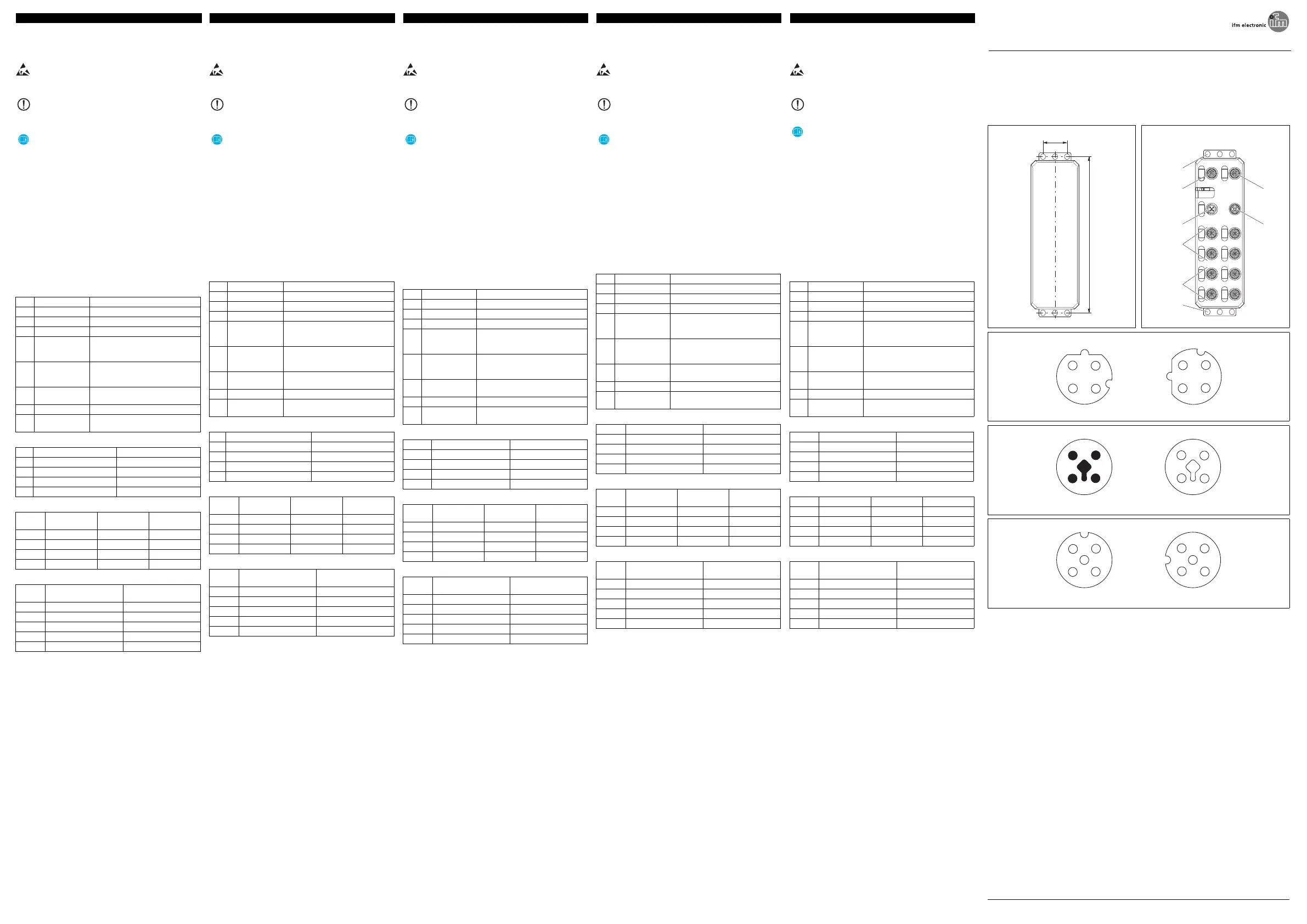
5.Anschlüsse auf dem Gerät ()
6.Pin-Belegung EtherNet ()
7.Pin-Belegung PWR ()
8.Pin-Belegung der Ports ()
ACHTUNG:
Beachten Sie die notwendigen Vorsichtsmaßnahmen bei
der Handhabung elektrostatisch gefährdeter
Bauelemente (EN61340-5-1 und IEC61340-5-1)!
ACHTUNG: Elektronikschäden bei Überlastung
Das Gerät ist für eine Spannung von 24VDC ausgelegt.
Betreiben Sie das Gerät nicht mit höherer Spannung.
Beachten Sie unbedingt auch die weiterführenden
Informationen im Datenblatt und im Anwenderhandbuch.
AnschlussBedeutung
1FEFunktionserde
2Port 1 (X21)EtherNet Port 1
3Port 2 (X22)EtherNet Port 2
4PWR IN (X31)Spannungsversorgung IN
(Logikspannung und IO-Link-Ports
und digitale Eingänge)
5PWR OUT (X32)Spannungsversorgung OUT
(Logikspannung und IO-Link-Ports
für weitere Geräte)
6IO-Link-A-Ports
(X01 ... X04)
IO-Link-A-Ports 1 ... 4
7IN (X01 ... X04)Digitale Eingänge 1 ... 4
8IO-Link-B-Ports
(X05 ... X08)
IO-Link-B-Ports 1... 4
PinEtherNet Port 1 (X21)EtherNet Port 2 (X22)
1TX+TX+
2RX+RX+
3TX-TX-
4RX-RX-
PinPWR IN (X31)PWR IN (X32)Aderfarben
1+24 V DC (U
S
)+24 V DC (U
S
)Braun
2GND (U
A
)GND (U
A
)Weiß
3GND (U
S
)GND (U
S
)Blau
4+24 V DC (U
A
)+24 V DC (U
A
)Schwarz
PinIO-Link-A-Ports
(X01 ... X04)
IO-Link-B-Ports
(X05 ... X08)
124 V DC (L+)24 V DC (L+)
2DI24 V DC (U
A
)
3GND (L-)GND (L-)
4C/QC/Q
5Nicht belegtGND (U
A
)
U
S
:18 V DC ... 31,2 V DC
(180 mA ± 15 % bei 24 V DC)
U
A
:18 V DC ... 31,2 V DC
(28 mA ± 15 % bei 24 V DC)
Outputs:18 V DC ... 31,2 V DC
(8 x 200 mA /max. 1,6 A)
Umgebungstemperatur:-25°C≤T
U
≤+60°C
AL1020: 7391035/02
30
198,5
ETH1ETH2
X21X22
PWR INPWR OUT
X31X32
X01X02
X03X04
X05X06
X07X08
1
1
2
3
4
5
6-7
8
1
2
3
4
X21
2
3
4
1
X22
X32X31
4
3
2
1
4
3
2
1
X01, X03, X05, X07
2
3
4
5
1
X02, X04, X06, X08
2
3
4
5
1
DE
DEUTSCHENGLISHFRANÇAISITALIANO
Einbauanweisung für den Elektroinstallateur
ENInstallation notes for electricians
FRInstructions d'installation pour l'électricien
ITIstruzioni di montaggio per l'elettricista installatore
2016-02-17
© ifm electronic gmbh 2016
Dispositivos de entrada/salida IO-Link para
EtherNet, carcasas de plástico
1.Advertencias de seguridad
2.Indicaciones de montaje
–Conecte el dispositivo a tierra a través de los tornillos de
fijación.
–Garantice el grado de protección IP67. Asegúrese de que los
cables de acometida estén herméticos y emplee capuchones
protectores para las conexiones que no estén en uso o los
extremos de cables con juntas de goma.
3.Montaje del dispositivo de plástico ()
Atornille el dispositivo en las bridas de fijación directamente
sobre una superficie de montaje plana.
4.Conectar los cables ()
Conecte los cables para el bus, la fuente de alimentación y los
puertos.
Si desea utilizar ambas funciones de los puertos (IO-Link/DI) de
forma paralela, use un repartidor Y.
5.Conexiones en el dispositivo ()
6.Asignación de pins EtherNet ()
7.Asignación de pins PWR ()
8.Asignación de pins de los puertos ()
IMPORTANTE:
¡Observe las medidas preventivas necesarias al manipular
elementos expuestos a peligro de descarga electrostática
(EN61340-5-1 y IEC61340-5-1)!
IMPORTANTE: daños a equipos electrónicos en caso
de sobrecarga
El dispositivo está diseñado para una tensión de 24VDC.
No use el dispositivo con una tensión mayor.
Tenga también siempre presentes las informaciones
adicionales de la hoja de datos y del manual de usuario.
ConexiónSignificado
1FETierra funcional
2Puerto 1 (X21)Puerto EtherNet 1
3Puerto 2 (X22)Puerto EtherNet 2
4PWR IN (X31)Alimentación de tensión IN (tensión
lógica, puertos IO-Link y entradas
digitales)
5PWR OUT (X32)Alimentación de tensión OUT
(tensión lógica y puertos IO-Link para
otros dispositivos)
6IO-Link-A-Ports
(X01 ... X04)
IO-Link-A-Ports 1 ... 4
7IN (X01 ... X04)Entradas digitales 1 ... 4
8IO-Link-B-Ports
(X05 ... X08)
Puertos 1... 4 IO-Link-B
PinPuerto EtherNet 1 (X21)Puerto EtherNet 2 (X22)
1TX+TX+
2RX+RX+
3TX-TX-
4RX-RX-
PinPWR IN (X31)PWR IN (X32)Colores del
conductor
1+24 V DC (U
S
)+24 V DC (U
S
)Marrón
2GND (U
A
)GND (U
A
)Blanco
3GND (U
S
)GND (U
S
)Azul
4+24 V DC (U
A
)+24 V DC (U
A
)Negro
PinIO-Link-A-Ports
(X01 ... X04)
IO-Link-B-Ports
(X05 ... X08)
124 V DC (L+)24 V DC (L+)
2DI24 V DC (U
A
)
3GND (L-)GND (L-)
4C/QC/Q
5no ocupadoGND (U
A
)
ESInstrucciones de montaje para el instalador eléctrico
PNR 106519 - 02
Produktspezifikationen
| Marke: | IFM |
| Kategorie: | Nicht kategorisiert |
| Modell: | AL1020 |
Brauchst du Hilfe?
Wenn Sie Hilfe mit IFM AL1020 benötigen, stellen Sie unten eine Frage und andere Benutzer werden Ihnen antworten
Bedienungsanleitung Nicht kategorisiert IFM

16 März 2026
11 März 2026
10 März 2026
10 März 2026
10 März 2026
9 März 2026
9 März 2026
9 März 2026
9 März 2026
8 März 2026
Bedienungsanleitung Nicht kategorisiert
Neueste Bedienungsanleitung für -Kategorien-
3 April 2026
3 April 2026
3 April 2026
3 April 2026
3 April 2026
3 April 2026
3 April 2026
3 April 2026
3 April 2026
3 April 2026