Lutron Caseta PD-6ANS Bedienungsanleitung
Lutron
Nicht kategorisiert
Caseta PD-6ANS
Lies die bedienungsanleitung für Lutron Caseta PD-6ANS (6 Seiten) kostenlos online; sie gehört zur Kategorie Nicht kategorisiert. Dieses Handbuch wurde von 3 Personen als hilfreich bewertet und erhielt im Schnitt 4.7 Sterne aus 2 Bewertungen. Hast du eine Frage zu Lutron Caseta PD-6ANS oder möchtest du andere Nutzer dieses Produkts befragen? Stelle eine Frage
Seite 1/6

ON
ON
ON
ON
OFF
ON
ON
ON
ON
OFF
OFF
OFF
OFF
ON
OFF
OFF
OFF
OFF
ON
ON
ON
ON
OFF
OFF
OFF
OFF
quick-start guide
In-wall switch
Welcome—and thank you for purchasing a Caséta
Wireless in-wall switch. In order to control your lights
from an app or remote, you’ll need to replace an existing
switch with a Caséta Wireless in-wall switch.
We hope you enjoy the convenience of Caséta Wireless!
Contents supplied
Double your warranty
In-wall switch
(PD-6ANS)
Tools you’ll need
Flat-head screwdriver
Wire connectors (5)
Phillips-head screwdriver
Pliers
Screws (2)
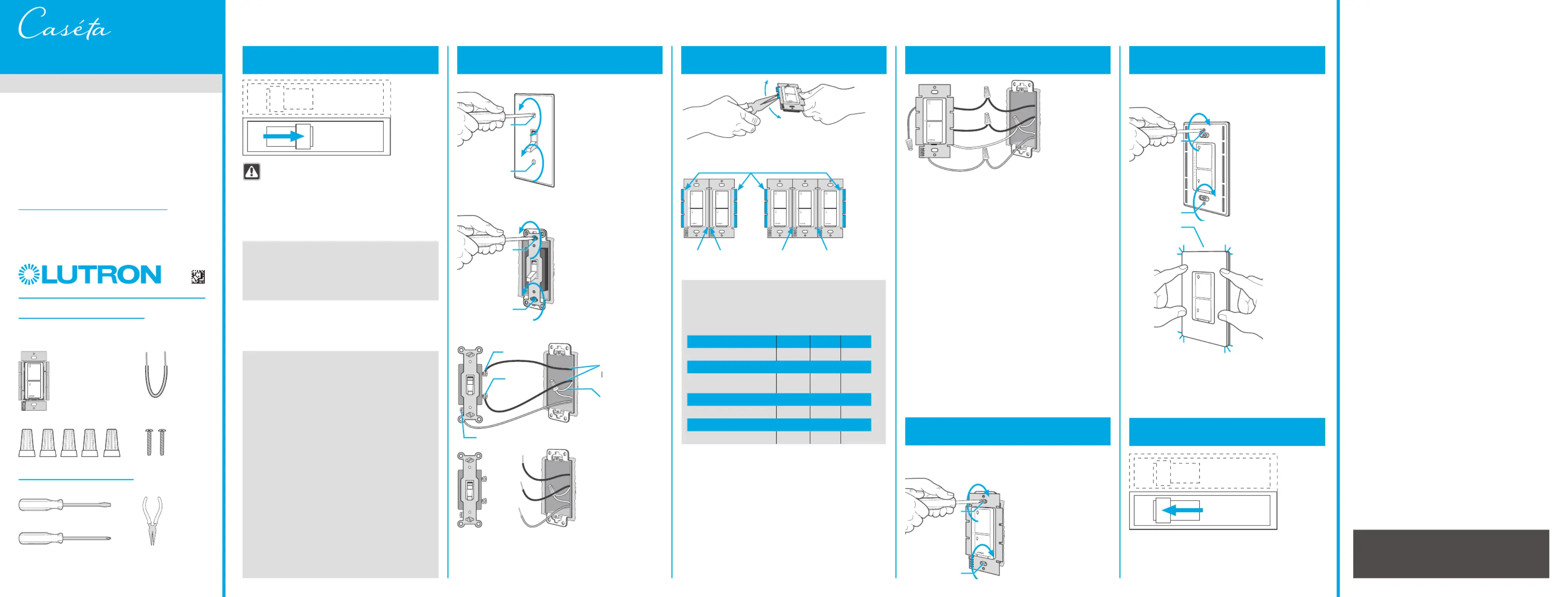
Installation for lights with one wall switch (single-pole)
Installing your switch
WARNING: SHOCK HAZARD
May result in serious injury or death. Turn off
power at circuit breaker or fuse before installing.
1
Turn power off at circuit breaker!
4
Connect the switch
5
Mount the switch
6
Attach the wallplate
7
Turn power on at circuit breaker
2
Remove existing switch from wall
Remove the wallplate from switch.
3
Remove side sections (if necessary)
Remove the switch and pull it away from the wall.
* If your light has more than one switch (called a 3-way),
please visit www.casetawireless.com/3way
Bend back
and forth.
3
5
1
4
6
Ground
Ground
Ground
7
2
Disconnect all three wires* from the switch.
1 Connect the bare copper (or green) “ground” wire
from the wallbox to the green wire on the switch
using a wire connector.
2 Connect the load wire from the wallbox to the red
wire on the switch using a wire connector.
3 Connect the hot wire from the wallbox to the black
wire on the switch using a wire connector.
4 Connect the neutral wire from the wallbox to
the white wire on the switch (neutral connection
required).
5 Cap the blue wire with a wire connector.*
* Note: The blue wire is only used in 3-way
installations. See www.casetawireless.com/3way
for more information.
Do not remove outside side sections on
switches at the end of gang.
Each switch has inside
side sections removed.
Switch at middle has all
side sections removed.
Attach the adapter to the switch using the
screws provided and snap on the wallplate.
‘snap’
(If you installed the switch next to other switches or
dimmers, you’ll need to install a wallplate with the
correct size / number of openings to accommodate all
the devices.)
Use the screws provided.
Love Caséta Wireless products? Have ideas
for making them better? Tell us what you think
and we’ll extend your warranty by 1 year.
www.casetawireless.com/register
CAUTION
Use only with permanently installed lighting loads or
with general purpose fan loads.
Codes
Install in accordance with all national and local
electrical codes.
Grounding
When no “grounding means” exist in wallbox, the
National Electrical Code (NEC ) allows a control to ®
be installed as a replacement if 1) a nonmetallic,
noncombustible faceplate is used with nonmetallic
attachment screws or 2) the circuit is protected by a
ground fault circuit interrupter (GFCI). When installing
a control according to these methods, cap or remove
green wire before screwing control into wallbox.
FCC/IC Information
This device complies with part 15 of the FCC Rules and Industry Canada
license-exempt RSS standard(s). Operation is subject to the following two
conditions: (1) This device may not cause interference, and (2) this device
must accept any interference, including interference that may cause undesired
operation. Modifications not expressly approved by Lutron Electronics Co.,
Inc. could void the user’s authority to operate this equipment.
Note: This equipment has been tested and found to comply with the limits for
a Class B digital device, pursuant to part 15 of the FCC Rules. These limits
are designed to provide reasonable protection against harmful interference
in a residential installation. This equipment generates, uses and can radiate
radio frequency energy and, if not installed and used in accordance with
the instructions, may cause harmful interference to radio communications.
However, there is no guarantee that interference will not occur in a particular
installation. If this equipment does cause harmful interference to radio or
television reception, which can be determined by turning the equipment off
and on, the user is encouraged to try to correct the interference by one or
more of the following measures:
—Reorient or relocate the receiving antenna.
—Increase the separation between the equipment and receiver.
— Connect the equipment into an outlet on a circuit different from that to which
the receiver is connected.
—Consult the dealer or an experienced radio/TV technician for help.
1
2
1
2
Wireless
Warranty
For warranty information, please visit
www.casetawireless.com/warranty
P/N 0301799 REV B
3
Important note:
Removing side sections reduces the switch’s maximum
wattage rating. See the chart below for maximum load
information.
Maximum load derating chart (120 V~ 50/60 Hz)
Side sections removed 1 side 2 sidesNone
LED, & Fluorescent
1
6 A 6 A 5 A
or
Incandescent, Halogen,
& ELV
720 W 720 W 600 W
or
MLV
2
720 VA 720 VA 600 VA
or
General Purpose Fan 3.6 A 3.6 A 3.6 A
Some lights have one wall switch, while others
have two or more wall switches (such as stair
lights, which have a switch at both the top
and bottom of the stairs). We’ve included
instructions for lights with one wall switch
(called a single pole). If your light has more than
one switch (called a 3-way), please visit
www.casetawireless.com/3way for
complete installation instructions and how-to
videos.
Important note:
1
The in-wall switch is UL Listed for use with all magnetic and R
electronic fluorescent ballasts.
2
The maximum lamp wattage is determined by the efficiency of
the transformer, with 70%–85% as typical. For actual transformer
efficiency, contact either the fixture or transformer manufacturer.
The total VA rating of the transformer(s) shall not exceed the VA
rating of the in-wall switch.
1
2
3
5
4
Note the
hot and
oad wires
Neutral
connection
required
Black
Red
Jumper wire
For wiring diagrams, please visit
www.casetawireless.com/wiring
Contractor note:

x3
Hold for 6 seconds
until LED starts
blinking
LED—up to 6 A
Incandescent / Halogen—up to 720 W
Supported Loads (120 V~)
Using your Caséta Wireless kit (sold separately)
1
Press and hold “off” button on the switch
2
Press and hold “off” button on remote
Pairing the switch and
Pico remote control
Go to www.casetawireless.com/support for
additional troubleshooting suggestions.
Symptoms Probable cause and action
Light does not
turn on or in-wall
switch LED does
not light up.
• Red and black wires on the
switch are reversed. (See
steps 4.2 and 4.3 on the
previous page)
• Light bulb(s) burned out.
• Breaker is OFF or tripped.
• Light not properly installed.
• Wiring error.
• FASS on the switch is in the
Off position.
Light does not
respond to Pico ®
remote control.
• The switch failed to pair with
Pico remote control; see Pairing
the switch and Pico remote
control.
• The switch is already at the light
level the Pico remote control is
sending.
• The Pico remote control is
outside the 30 ft (9 m) operating
range.
• The Pico remote control battery
is low.
• The Pico remote control battery
is installed incorrectly.
For advanced features, tips for using Caséta Wireless products with LEDs, the complete Caséta Wireless product line,
and more, please visit www.casetawireless.com/features
Replacing light bulbs using FASS
Pull the FASS out on the in-wall switch to remove
power at the light socket.
Lutron, the Lutron logo, Caséta, FASS, the Caséta logo, Smart Bridge, and
Pico are trademarks or registered trademarks of Lutron Electronics Co., Inc.
in the US and/or other countries. Apple is a trademark of Apple Inc.,
registered in the U.S. and other countries. App Store is a service mark of
Apple Inc. All other product names, logos, and brands are property of their
respective owners.
© 2014–2021 Lutron Electronics Co., Inc
Lutron Electronics Co., Inc.
7200 Suter Road
Coopersburg, PA 18036-1299, U.S.A.
Troubleshooting
Hold for 6 seconds
until lights flash 3 times.
Device Ratings
In-wall switch
PD-6ANS
120 V 50/60 Hz~
Important notes:
1. For indoor use only.
2. Operate between 32 ˚F (0 ˚C) and 104 ˚F (40 ˚C).
Repeat steps to pair other Pico remote controls.
Pico remote control (sold separately)
On
Off
FASS
Front Accessible
Service Switch
In-wall switch
With a smartphone or tablet (Smart Bridge required, sold separately)
1
2
The Lutron app will walk you through
setting up your devices.
Download the Lutron app
www.casetawireless.com/LutronApp
Launch the Lutron app
The Caséta Wireless switch can be controlled from a smartphone
when used with the Lutron Smart Bridge.
If you are using the switch and remote control with the Lutron
Smart Bridge follow the instructions below.
Search for “Lutron App”
3
Use the Lutron® app to complete ALL remaining steps
Lutron Smart Bridge
Note: If you are using the switch and remote control with
another manufacturer’s bridge, please refer to that manufacturer’s
instructions for set-up.
Lutron app
Without a smartphone or tablet
(Smart Bridge not required)
MLV—up to 720 VA /575 W
Control
three ways
Add devices
• Pico remote controls
• Dimmers
• Shades
Schedule
your lights
Connect
while away
ELV—up to 720 W
Fluorescent—up to 6 A
General Purpose Fan—up to 3.6 A
Using your controls
On
Off

1
2
1
2
ENCENDIDO
ENCENDIDO
ENCENDIDO
ENCENDIDO
APAGADO
ENCENDIDO
ENCENDIDO
ENCENDIDO
ENCENDIDO
AP
AP
AP
APAGADO
AGADO
AGADO
AGADO
ENCENDIDO
AP
AP
AP
APAGADO
AGADO
AGADO
AGADO
ENCENDIDO
ENCENDIDO
ENCENDIDO
ENCENDIDO
AP
AP
AP
APAGADO
AGADO
AGADO
AGADO
Interruptor electrónico de pared
1
¡Corte la corriente del cortacircuitos!
3
5
1
4
6
Tierra
Tierra
7
2
guía de inicio rápido
Contenido suministrado
Doble su garantía
Interruptor electrónico de pared
(PD-6ANS)
Herramientas que necesitará
Destornillador de cabeza plana
Conectores de cables (5)
Destornillador Phillips
Alicates
Tornillos (2)
¿Le encantan los productos Caséta
Wireless? ¿Tiene alguna idea para
mejorarlos? Cuéntenos su opinión y
extenderemos la garantía por 1 año.
www.casetawireless.com/register
ADVERTENCIA: RIESGO DE
DESCARGA ELÉCTRICA.
Puede resultar en lesiones graves o la muerte.
Corte la corriente del cortacircuitos o fusible
antes de instalar.
Algunas luces tienen un interruptor de
pared, mientras que otras tienen dos o
más interruptores de pared (como luces de
escaleras, que tienen un interruptor tanto al
inicio como al final de las escaleras). Hemos
incluido instrucciones para luces con un
interruptor de pared (llamado unipolar). Si su luz
tiene más de un interruptor (llamado de 3vías),
visite www.casetawireless.com/3way
para obtener las instrucciones completas de
instalación y los videos instructivos.
Nota importante:
Instalación de luces con un interruptor de pared (unipolar)
Cómo instalar el interruptor
2
Retire el interruptor actual de la pared
Retire la placa de pared del interruptor.
Retire el interruptor y aléjelo de la pared.
* Si su luz tiene más de un interruptor (llamado de 3vías),
visite www.casetawireless.com/3way
Desconecte los tres cables* del interruptor.
3
Retire las secciones laterales
(en caso de ser necesario) 4
Conecte el interruptor
5
Coloque el interruptor
1 Conecte el cable a tierra de cobre sin protección
(o verde) desde la caja de pared al cable verde del
interruptor utilizando un conector de cable.
2 Conecte el cable de carga de la caja de pared al cable
rojo del interruptor utilizando un conector de cable.
3 Conecte el cable vivo de la caja de pared al cable
negro del interruptor utilizando un conector de cable.
4 Conecte el cable neutro de la caja de pared al cable
blanco del interruptor (se requiere conexión a neutro).
5 Tape el cable azul con un conector de cable.*
Nota: El cable azul solo se utiliza en instalaciones
de tres vías. Para más información
vea www.casetawireless.com/3way
Use los tornillos proporcionados.
Tierra
6
Coloque la placa de pared
7
Encienda la corriente
del cortacircuitos
Conecte el adaptador al interruptor con los tornillos
suministrados y encájelo en la placa de pared.
(Si instaló el interruptor al lado de otros interruptores
oatenuadores, debe instalar una placa de pared que
tenga la cantidad correcta de orificios y del tamaño
correcto para instalar todos los dispositivos.)
PRECAUCIÓN
Usar únicamente con cargas de iluminación instaladas
permanentemente o con cargas de ventilador para
propósitos generales.
Códigos
Instale de acuerdo con todos los códigos eléctricos
nacionales y locales.
Conexión a tierra
Cuando no exista ningún medio de conexión a
tierra en la caja de pared, el NEC (Código Eléctrico ®
Nacional) permite la instalación de un control como
reemplazo si 1) se usa una placa frontal incombustible
que no sea metálica con tornillos de sujeción no
metálicos o 2) el circuito está protegido por un GFCI
(interruptor de circuito por falla a tierra). Al instalar un
control de acuerdo con estos métodos, tape o retire
el cable verde antes de atornillar el control a la caja de
pared.
Información de la FCC/IC
Este dispositivo cumple con la parte 15 de las reglas de la FFC (Comisión
Federal deComunicaciones) y con las normas RSS de IC (Industry Canada)
para dispositivos exentos de licencia. La operación está sujeta a las dos
condiciones siguientes: (1)Estedispositivo no debe causar interferencia
perjudicial y (2) este dispositivo debe aceptar cualquier interferencia recibida,
incluyendo las que pueden causar una operación indeseada. Cualquier cambio
o modificación sin la aprobación explícita deLutron Electronics Co., Inc. puede
anular la autorización del usuario para operar elequipo.
Nota: Este equipo p3-ha sido probado y se comprobó que cumple con los límites
para dispositivos digitales de ClaseB, de acuerdo con la Parte15 de las
Reglas de la FCC. Estos límites se han diseñado para proveer una protección
razonable contra interferencias dañinas en una instalación residencial. Este
equipo genera, usa ypuede emitir energía de radiofrecuencia y si no se instala
yutiliza de acuerdo con las instrucciones, puede causar interferencia dañina en
las comunicaciones de radio. Sin embargo, no hay garantía de que no ocurrirá
interferencia en una instalación determinada. Si este equipo causa interferencia
dañina en la recepción de la radio ola televisión, que se puede determinar
encendiendo y apagando el equipo, elusuario puede tratar de corregir la
interferencia mediante uno o más de los siguientes procedimientos:
—Cambiar la orientación o ubicación de la antena receptora.
—Aumentar la separación entre el equipo y el receptor.
— Conectar el equipo a un receptáculo que esté en un circuito diferente al del
receptor.
— Consultar al distribuidor o a un técnico experimentado en radio/TV para
obtener ayuda.
Garantía
Para obtener información sobre la garantía, visite
www.casetawireless.com/warranty
Lea antes de instalar.
Bienvenido, y gracias por comprar el interruptor de
pared Caséta Wireless. Para controlar sus luces desde
una aplicación o un control remoto, deberá reemplazar
un interruptor existente por un Interruptor de pared
Caséta Wireless.
¡Esperamos que disfrute la comodidad de
Caséta Wireless!
Wireless
3
Doble hacia atrás y hacia delante.
No quite las secciones laterales externas
de los interrupores al final de la conexión.
Cada interruptor tiene
las secciones laterales
internas quitadas.
El interruptor del medio
tiene todas las secciones
laterales quitadas.
Nota importante:
Cuando retira las secciones laterales, se reduce el vataje
derégimen máximo. Consulte el cuadro a continuación para
obtener la información de carga máximo.
Cuadro de reducción de carga máximo (120 V 50/60 Hz)~
Secciones laterales quitadas
Ninguna
1
lateral
2
laterales
LED, y Fluorescente
1
6 A 6 A 5 A
o
Incandescente, halógena,
y BVE
720 W 720 W 600 W
o
BVM
2
720 VA 720 VA 600 W
o
Fan de uso general 3.6 A 3.6 A 3.6 A
1
El interruptor de la pared figura en la lista UL y es adecuado R
para ser utilizado con todos los balastros fluorescentes
magnéticos y electrónicos.
2
El vataje máximo de la lámpara se determina según la eficacia
del transformador, siendo habitual un valor de entre 70% y 85%.
Para una eficacia real del transformador, póngase en contacto
con el fabricante de la luminaria o transformador. La potencia
total de VA del transformador no deberá superar la potencia de
VA del interruptor dentro de la pared.
‘chasquido’
P/N 0301799 REV B
1
2
3
5
4
Negro
Rojo
Tenga en
cuenta los
cables de
ínea y carga
Se requiere
conexión a
neutro
Cable de puente
Por los diagramas de cableado, visite
www.casetawireless.com/wiring
Nota para los contratistas:
Produktspezifikationen
Marke: | Lutron |
Kategorie: | Nicht kategorisiert |
Modell: | Caseta PD-6ANS |
Brauchst du Hilfe?
Wenn Sie Hilfe mit Lutron Caseta PD-6ANS benötigen, stellen Sie unten eine Frage und andere Benutzer werden Ihnen antworten
Bedienungsanleitung Nicht kategorisiert Lutron
28 August 2025
28 August 2025
27 August 2025
27 August 2025
27 August 2025
25 Juli 2025
Bedienungsanleitung Nicht kategorisiert
- CTOUCH
- PVI
- Revox
- OXI Instruments
- Yeastar
- Code
- IOptron
- Zodiac
- Bayco
- EasyMaxx
- Arista
- Murideo
- Argus
- Robust
- Absima
Neueste Bedienungsanleitung für -Kategorien-
28 August 2025
28 August 2025
28 August 2025
28 August 2025
28 August 2025
28 August 2025
28 August 2025
28 August 2025
28 August 2025
28 August 2025