Microchip HV861 Bedienungsanleitung
Microchip Nicht kategorisiert HV861
Lies die bedienungsanleitung für Microchip HV861 (60 Seiten) kostenlos online; sie gehört zur Kategorie Nicht kategorisiert. Dieses Handbuch wurde von 17 Personen als hilfreich bewertet und erhielt im Schnitt 4.3 Sterne aus 8 Bewertungen. Hast du eine Frage zu Microchip HV861 oder möchtest du andere Nutzer dieses Produkts befragen? Stelle eine Frage
Seite 1/60
2023 Microchip Technology Inc. and its subsidiariesDS20005911A-page 1
HV861
Features
•Adjustable Output Regulation for Dimming
•Lamp Fade-in/Fade-out Capability
•Low Audible Noise
•180 V
PP
Output Voltage for Higher Brightness
•1.5V Enable Input Logic High
•Single-cell Lithium Ion-compatible
•One Miniature Inductor to Power both Lamps
•Separately Adjustable Lamp and Converter
Frequencies
•Split Supply Capability
Applications
•Dual Display Cellular Phones
•Keypad and LCD Backlighting
•Personal Digital Assistant (PDA)
•Handheld Wireless Communication Products
•Global Positioning Systems (GPS)
General Description
The HV861 is a low-noise dimmable high-voltage dual EL
lamp driver designed for driving two electroluminescent
(EL) lamps with a combined area of 5 in
2
. The input
supply voltage range is from 2.5V to 4.5V. Enable input
logic high can go as low as 1.5V, which allows logic
interface operating from typical 1.8V supplies. The
device is designed to minimize audible noise emitted by
the EL lamps.
The device uses a single inductor and a minimum
number of passive components. With the internal
reference voltage, the regulated output voltage is at a
nominal value of 90V. The EL lamps therefore see ±90V.
The two EL lamps can be turned on and turned off using
two CMOS logic inputs, EN1 and EN2. The driver is
disabled when both EN1 and EN2 are at logic low.
The HV861 has two internal oscillators, a switching
MOSFET, and two high-voltage EL lamp driver
H-bridges. Each driver has its own half-bridge common
output, COM1 and COM2, which significantly minimizes
the DC offset seen by the EL lamp. The frequency for the
switching MOSFET is set by an external resistor
connected between the R
SW-Osc
pin and the supply pin,
V
DD
. The EL lamp driver frequency is set by an external
resistor connected between the R
EL-Osc
pin and the V
DD
pin. An external inductor is connected between the L
X
and V
DD
pins or V
IN
for split supply applications.
Depending upon the EL lamp sizes, a 1 nF to 10 nF
capacitor is connected between the C
S
and ground. As
the switching MOSFET charges the external inductor
and discharges it into the capacitor at C
S
, the voltage at
C
S
starts to increase. Once the voltage at C
S
reaches a
nominal value of 90V, the switching MOSFET is turned
off to conserve power.
EL lamp dimming can be accomplished by applying a
PWM logic signal to the PWM pin. The EL lamp
brightness will be inversely proportional to the PWM duty
cycle. The HV861 can also slowly turn on or turn off the
EL lamp, giving a fade on/off appearance.
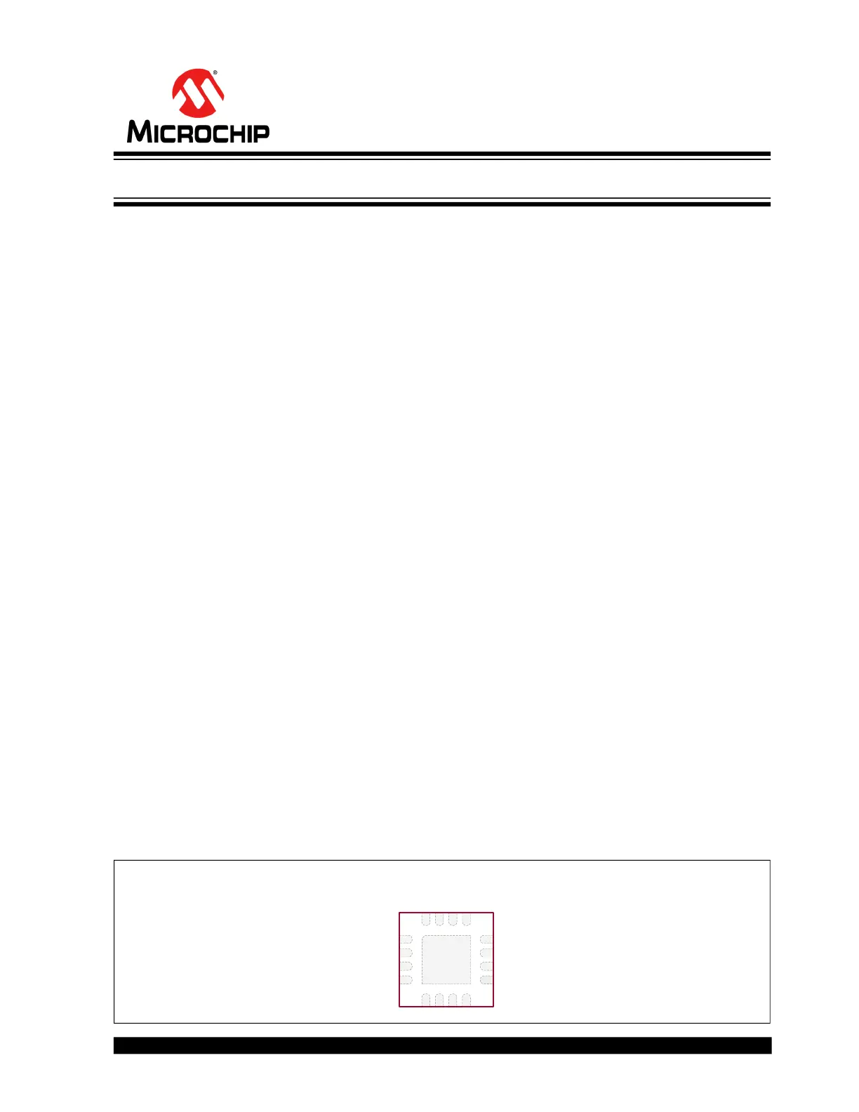
Package Type
See Table2-1 for pin information.
16-lead WQFN
(Top view)
1
12
2
3
4
56
7
8
9
10
11
1314
15
16
VREFVREGVOUTPWM
EL1
COM1
COM2
EL2
REL-Osc
RSW-Osc
VDD
EN1
EN2GND
LXCS
Low-Noise Dimmable Dual EL Lamp Driver
Produktspezifikationen
| Marke: | Microchip |
| Kategorie: | Nicht kategorisiert |
| Modell: | HV861 |
Brauchst du Hilfe?
Wenn Sie Hilfe mit Microchip HV861 benötigen, stellen Sie unten eine Frage und andere Benutzer werden Ihnen antworten
Bedienungsanleitung Nicht kategorisiert Microchip

30 Januar 2026
23 Januar 2026
23 Januar 2026
20 Januar 2026
19 Januar 2026
15 Januar 2026
14 Januar 2026
14 Januar 2026
3 Dezember 2025
2 Dezember 2025
Bedienungsanleitung Nicht kategorisiert
Neueste Bedienungsanleitung für -Kategorien-
3 April 2026
3 April 2026
3 April 2026
3 April 2026
3 April 2026
3 April 2026
3 April 2026
3 April 2026
3 April 2026
3 April 2026