Microchip SY10EP16V Bedienungsanleitung
Microchip Nicht kategorisiert SY10EP16V
Lies die bedienungsanleitung für Microchip SY10EP16V (8 Seiten) kostenlos online; sie gehört zur Kategorie Nicht kategorisiert. Dieses Handbuch wurde von 31 Personen als hilfreich bewertet und erhielt im Schnitt 4.5 Sterne aus 6 Bewertungen. Hast du eine Frage zu Microchip SY10EP16V oder möchtest du andere Nutzer dieses Produkts befragen? Stelle eine Frage
Seite 1/8
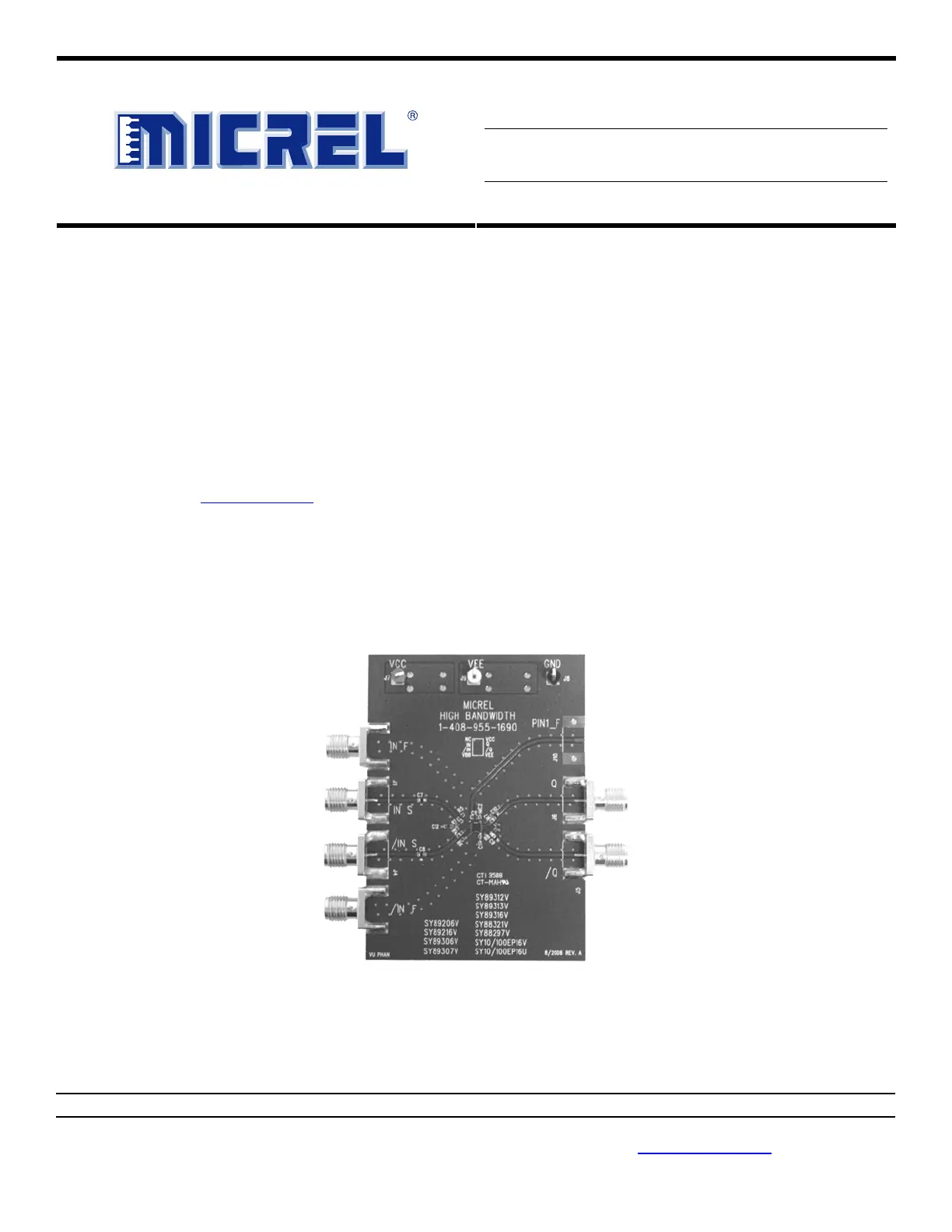
SY10/100EP16U and SY10/100EP16V
Evaluation Board
2.5V/3.3V/5V Precision ECL Differential
Receiver/Driver
Micrel Inc. • 2180 Fortune Drive • San Jose, CA 95131 • USA • tel +1 (408) 944-0800 • fax + 1 (408) 474-1000 • http://www.micrel.com
December 2008
M9999-121708-A
or (408) 955-1690
General Description
The SY10/100EP16U and SY10/100EP16V evaluation
boards are designed for convenient set-up and quick
evaluation. They allow the user to evaluate the part over
the full voltage-range of the part without requiring any
modification to the board.
The evaluation board standard configuration is AC-coupled
inputs with AC-coupled outputs for direct interface to a
50Ω-compatible oscilloscope. For applications that require
a DC-coupled configuration, step-by-step instructions for
modifying the board are included.
All datasheets and support documentation can be found at
Micrel’s web site at: www.micrel.com
.
Features
•SY10/100EP16UM ECL output
•SY10/100EP16VM ECL output
•Single 2.5V, 3.3V, or 5V power supply
•AC-coupled configuration for ease-of-use
•I/O interface includes on-board termination
•Fully assembled and tested
•Reconfigurable for DC-coupled operation
Applications
• SY10/100EP16U 2.5/3.3V Precision ECL Differential
Receiver/Driver
•SY10/100EP16V 3.3V/5V Precision ECL Differential
Receiver/Driver
___________________________________________________________________________________________________________
Evaluation Board
Produktspezifikationen
| Marke: | Microchip |
| Kategorie: | Nicht kategorisiert |
| Modell: | SY10EP16V |
Brauchst du Hilfe?
Wenn Sie Hilfe mit Microchip SY10EP16V benötigen, stellen Sie unten eine Frage und andere Benutzer werden Ihnen antworten
Bedienungsanleitung Nicht kategorisiert Microchip

30 Januar 2026
23 Januar 2026
23 Januar 2026
20 Januar 2026
19 Januar 2026
15 Januar 2026
14 Januar 2026
14 Januar 2026
3 Dezember 2025
2 Dezember 2025
Bedienungsanleitung Nicht kategorisiert
Neueste Bedienungsanleitung für -Kategorien-
3 April 2026
3 April 2026
3 April 2026
3 April 2026
3 April 2026
3 April 2026
3 April 2026
3 April 2026
3 April 2026
3 April 2026