Microchip SY89873L Bedienungsanleitung
Microchip Nicht kategorisiert SY89873L
Lies die bedienungsanleitung für Microchip SY89873L (11 Seiten) kostenlos online; sie gehört zur Kategorie Nicht kategorisiert. Dieses Handbuch wurde von 24 Personen als hilfreich bewertet und erhielt im Schnitt 4.8 Sterne aus 7 Bewertungen. Hast du eine Frage zu Microchip SY89873L oder möchtest du andere Nutzer dieses Produkts befragen? Stelle eine Frage
Seite 1/11
1
Precision Edge
®
SY89873L
Micrel, Inc.
M9999-082407
[email protected] or (408) 955-1690
DESCRIPTION
Guaranteed AC performance
•> 2.0GHz f
MAX
output toggle
•> 3.0GHz f
MAX
input
•<800ps t
PD
(matched-delay between banks)
•<15ps within-device skew
•<190ps rise/fall time
Low jitter design
•<1ps
RMS
cycle-to-cycle jitter
Unique input termination and V
T
pin for DC-coupled
and AC-coupled inputs:any differential inputs
(LVPECL, LVDS, CML, HSTL)
Precision differential LVDS outputs
Matched delay:all outputs have matched delay,
independent of divider setting
TTL/CMOS inputs for select and reset/disable
Two LVDS output banks (matched delay)
•Bank A:Buffered copy of input clock (undivided)
•Bank B:Divided output (÷2, ÷4, ÷8, ÷16),
two copies
3.3V power supply
Wide operating temperature range:–40
°C to +85°C
Available in 16-pin (3mm
××
××
× 3mm) QFN package
FEATURES
3.3V, 2.0GHz ANY DIFF. IN-TO-LVDS
PROGRAMMABLE CLOCK DIVIDER
FANOUT BUFFER W/ INTERNAL TERMINATION
Precision Edge
®
SY89873L
APPLICATIONS
SONET/SDH line cards
Transponders
High-end, multiprocessor servers
Rev.: FAmendment: /0
Issue Date:February 2007
This 3.3V low-skew, low-jitter, precision LVDS output clock
divider accepts any high-speed differential clockinput (AC- or
DC-coupled)CML, LVPECL, HSTL orLVDSanddividesdown
the frequency using a programmabledivider ratio to create a
frequency-locked, lower speedversionof the input clock.The
SY89873Lincludes two output banks.Bank A is an exact
copyoftheinputclock(passthrough)withmatched
propagationdelay to BankB, the dividedoutput bank. Available
divider ratios are 2, 4, 8 and 16. In a typical 622MHz clock
system this wouldprovideavailability of 311MHz, 155MHz,
77MHz or 38MHz auxiliary clock components.
The differentialinput buffer has a uniqueinternal termination
designthat allows access to the terminationnetworkthrough
a VT pin. This feature allows the device to easily interface to
allAC- or DC-coupled differential logic standards.A V
REF-AC
reference is included forAC-coupledapplications.
The SY89873Lis part of Micrel’s high-speed Precision
Edge
®
timing and distributionfamily.For 2.5V applications,
considertheSY89872U.Forapplicationsthatrequirean
LVPECL output, consider the SY89871U.
The /RESET input asynchronously resets thedivider outputs
(Bank B).In the pass-through function(Bank A) the/RESET
synchronously enables or disables the outputs on the next
falling edge of IN (rising edge of /N). Refer to the Timing
Diagram.
All support documentation can be found on Micrel’s web
site at: www.micrel.com.
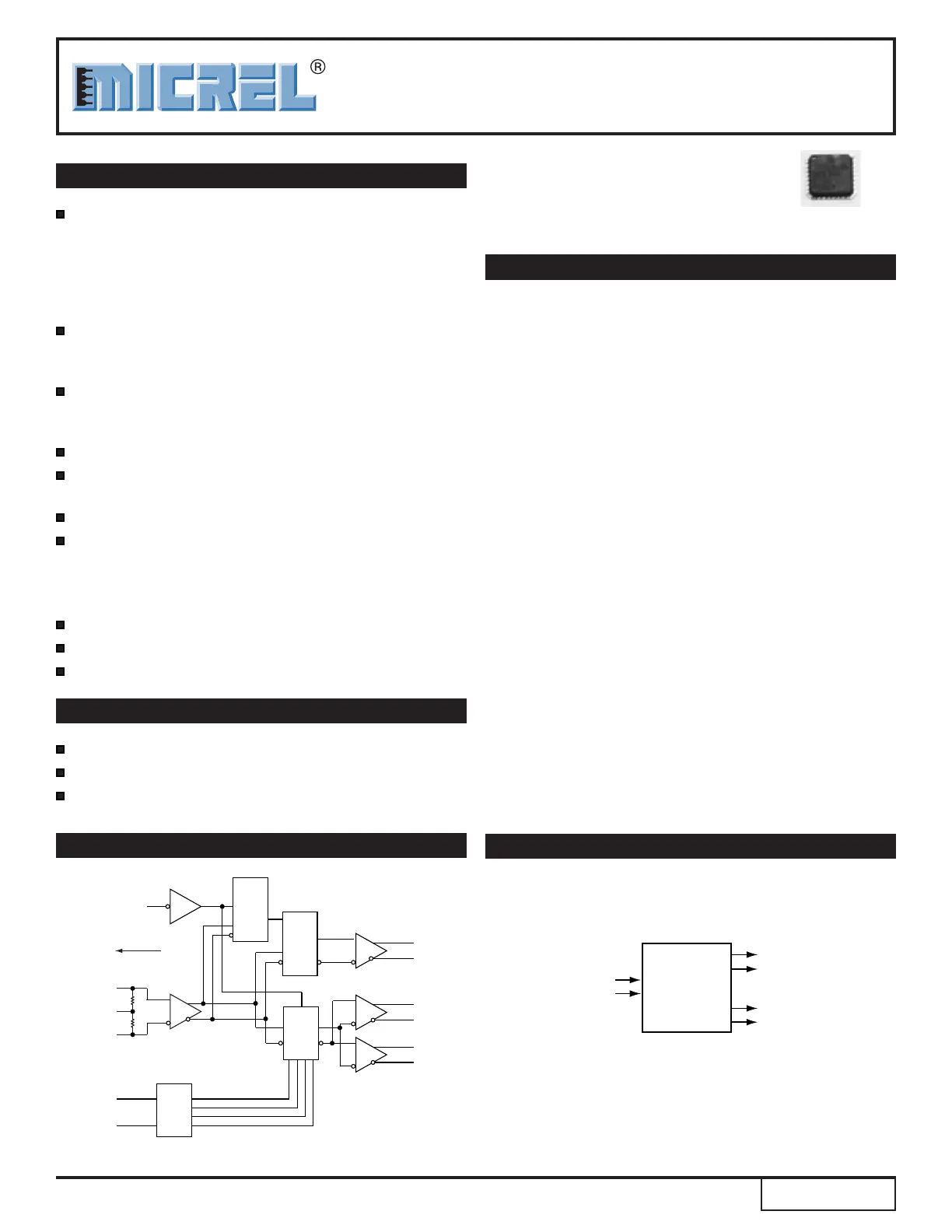
FUNCTIONAL BLOCK DIAGRAM
TYPICAL APPLICATION
IN
50Ω
50Ω
/IN
S0
S1
QB1
/QB1
QB0
/QB0
QA
/QA
/RESET
V
T
V
REF-AC
Divided
by
2, 4, 8
or 16
Decoder
Enable
FF
Enable
MUX
Precision Edge
®
IN
/IN
QA
/QA
622MHz LVDS
Clock Out
622MHz LVPECL
Clock In
622MHz/155.5MHz
SONET Clock Generator
Bank B: 155.5MHz: For OC-3 line card
Set to divide-by-4
Bank A: 622MHz: For OC-12 line card
Set to pass-through
155.5MHz LVDS
Clock Out
OC-12 or
OC-3
Clock Gen
QB
/QB
Precision Edge is a registered trademark of Micrel, Inc.
Produktspezifikationen
| Marke: | Microchip |
| Kategorie: | Nicht kategorisiert |
| Modell: | SY89873L |
Brauchst du Hilfe?
Wenn Sie Hilfe mit Microchip SY89873L benötigen, stellen Sie unten eine Frage und andere Benutzer werden Ihnen antworten
Bedienungsanleitung Nicht kategorisiert Microchip

30 Januar 2026
23 Januar 2026
23 Januar 2026
20 Januar 2026
19 Januar 2026
15 Januar 2026
14 Januar 2026
14 Januar 2026
3 Dezember 2025
2 Dezember 2025
Bedienungsanleitung Nicht kategorisiert
Neueste Bedienungsanleitung für -Kategorien-
3 April 2026
3 April 2026
3 April 2026
3 April 2026
3 April 2026
3 April 2026
3 April 2026
3 April 2026
3 April 2026
3 April 2026