Panasonic CY-VMD9000U Bedienungsanleitung
Panasonic
Nicht kategorisiert
CY-VMD9000U
Lies die bedienungsanleitung für Panasonic CY-VMD9000U (16 Seiten) kostenlos online; sie gehört zur Kategorie Nicht kategorisiert. Dieses Handbuch wurde von 2 Personen als hilfreich bewertet und erhielt im Schnitt 4.3 Sterne aus 1.5 Bewertungen. Hast du eine Frage zu Panasonic CY-VMD9000U oder möchtest du andere Nutzer dieses Produkts befragen? Stelle eine Frage
Seite 1/16

E
N
G
L
I
S
H
47
CY-VMD9000U
62
Installation Guide
WARNING
This installation information is designed for experienced installers and is not intend-
ed for non-technical individuals. It does not contain warnings or cautions of potential
dangers involved in attempting to install this product.
Any attempt to install this product in a motor car by anyone other than qualified
installer could cause damage to the electrical system and could result in serious per-
sonal injury or death.
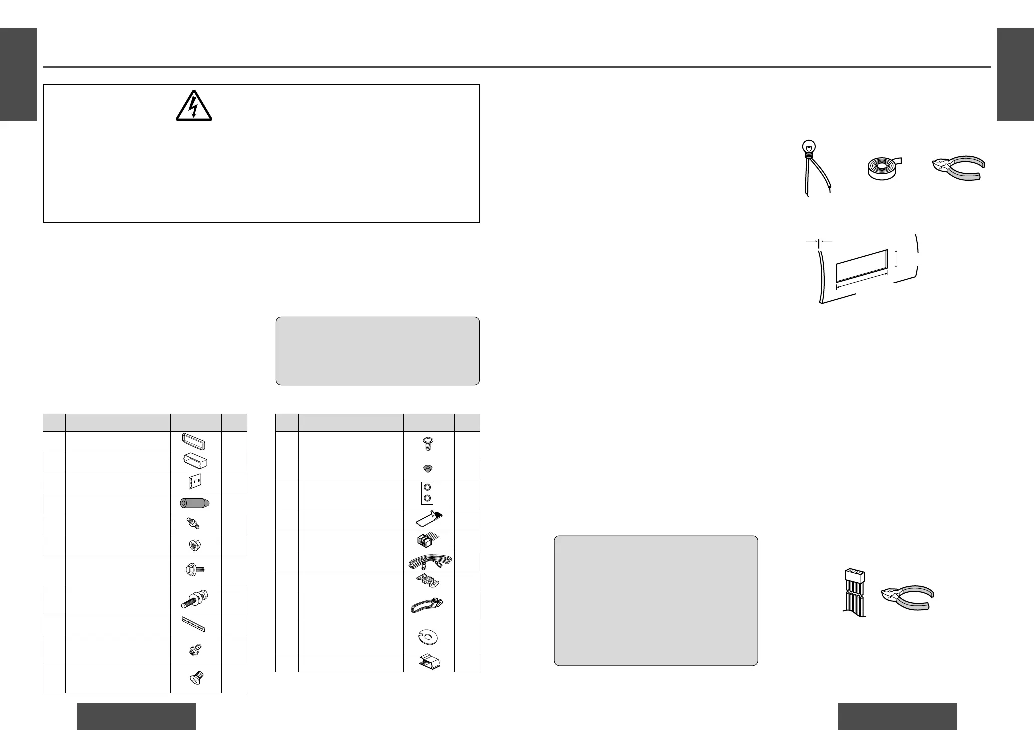
❐ Installation Hardware
❐ Overview
This product should be installed by a professional.
However, if you plan to install this unit yourself, your
first step is to decide where to install it. The instruc-
tions in these pages will guide you through the
remaining steps:
(Please refer to the “WARNING” statement
above.)
≥ Identify and label the car wires.
≥ Connect the car wires to the wires of the power
connector.
E
N
G
L
I
S
H
48
CY-VMD9000U
63
12 V DC test
bulb
Electrical tape Slide-cut
pliers
❐ Required Tools
You’ll need a screwdriver and the following:
❐ Before Installation
Warning
≥ Do not install the monitor in a location which
obstructs driving, visibility or which is prohibit-
ed by applicable laws and regulations.
If the monitor is installed in a location which
obstructs forward visibility or operation of the air
bag or other safety equipment or which interferes
with operation of the car, it may cause an acci-
dent.
≥ Never use bolts or nuts from the car’s safety
devices for installation.
If bolts or nuts from the wheel, brakes or other
safety devices are used for installation of the mon-
itor, it may cause an accident.
≥ Attach the wires correctly.
If the wiring is not correctly performed, it may
cause a fire or an accident. In particular, be sure to
run and secure the lead wire so that it does not get
tangled with a screw or the moving portion of a
seat rail.
≥ Use with 12 V DC negative ground car.
This unit is only for use with a 12 V DC negative
ground car. It cannot be used in large trucks or
diesel cars which are 24 V DC cars. If it is used in
the wrong type of car, it may cause a fire or an
accident.
Caution:
≥ This unit operates with a 12 V DC negative
ground auto battery system only. Do not
attempt to use it in any other system. Doing
so could cause serious damage.
Cautions:
≥ Use the specified fuse.
Be sure to always use the specified fuse. If a
fuse other than the specified fuse is used, it
may cause a fire or an accident.
≥ Do not damage the cord by pinching or
pulling it.
Do not pull or damage the cord. If the cord is
not treated properly, it will short out or be
severed and may cause a fire or an accident.
≥ Install the unit in the dashboard.
≥ Check the operation of the unit.
If you encounter problems, please consult your
nearest professional installer.
Before you begin installation, look for the following
items which are packed with your unit.
≥ Warranty Card…Fill this out promptly.
≥ Panasonic Servicenter List for Service Directory
…Keep for future reference in case the unit needs
servicing.
≥ Installation Hardware…Needed for monitor set-
ting.
❐ Dashboard Specifications
The first step in installation is to identify all the car
wires you’ll use when hooking up your LCD monitor.
As you identify each wire, we suggest that you label
it using masking tape and a permanent marker. This
will help avoid confusion when making connections
later.
Note:
≥Do not connect the power connector to the display
unit until you have made all connections. If there
are no plastic caps on the hooking wires, insulate
all exposed leads with electrical tape until you are
ready to use them. Identify the leads in the follow-
ing order.
Power Lead
If your car has a radio or is pre-wired for one:
Cut the connector wires one at a time from the plug
(leaving the leads as long as possible) so that you
can work with individual leads. Turn the ignition on
to the accessory position, and ground one lead of
the test bulb to the chassis.
❐ Identify All Leads
No. Item Diagram Q’ty
1 Trim plate 1
2 Mounting collar 1
3 Mounting spring 2
4 Rubber pad 1
5 Mounting bolt (M5) 1
6 Flange nut (M6) 1
7 Washer assembling hex.
bolt (M5
k
10 mm)
1
8 Washer assembling hex.
bolt (M6
k
20 mm)
1
9 Rear support strap 1
: Binding-head screw
(M5
k
6 mm)
2
; Flat-head screw
(M5
k
6 mm)
4
No. Item Diagram Q’ty
< Binding-head screw
(M4
k
3 mm)
4
= Spacer 2
> Double-faced adhesive 1
tape (for spacer) set
? Velcro tape 2
@ Power connector 1
A Reverse extension cord 1
B Clip connector 1
C Display unit/control unit
connecting cord
1
D Double-faced adhesive
tape (for speaker)
1
E Clamp 2
Thickness
Min.
3
/
16
q (4.75 mm)
Max.
7
/
32
q (5.56 mm)
2
3
/
32
q (53 mm)
7
5
/
32
q (182 mm)
Touch the other lead of the test bulb to each of the
exposed wires from the cut radio connector plug.
Touch one wire at a time until you find the outlet that
causes the test bulb to light.
Now turn the ignition off and then on. If the bulb also
turns off and on, that outlet is the car power lead.

E
N
G
L
I
S
H
50
CY-VMD9000U
65
E
N
G
L
I
S
H
49
CY-VMD9000U
64
Installation Guide (Continued)
If your car is not wired for an audio unit:
Go to the fuse block and find the fuse port for radio
(RADIO), accessory (ACC), or ignition (IGN).
Battery Lead
If your unit has a yellow lead, you will need to locate
the car’s battery lead. Otherwise you may ignore this
procedure. (The yellow battery lead provides contin-
uous power to maintain a clock, memory storage, or
other functions.)
If your car has a radio or is pre-wired for one:
With the ignition and headlights off, identify the car
battery lead by grounding one lead of the test bulb to
the chassis and checking the remaining exposed
wires from the cut radio connector plug.
If your car is not wired for an audio unit:
Go to the fuse block and find the fuse port for the
battery, usually marked BAT.
❐ Connect All Leads
Now that you have identified all the wires in the car,
you are ready to begin connecting them to the LCD
monitor wires. The wiring diagram (➡ pages 70, 71)
shows the proper connections and color coding of
the leads.
We strongly recommend that you test the unit
before making a final installation.
You can set the unit on the floor and make tempo-
rary connections to test the unit. Use electrical tape
to cover all exposed wires.
Important:
≥Connect the red power lead last, after you have
made and insulated all other connections.
Ground
Connect the black ground lead of the power connec-
tor to the metal car chassis.
Battery
Connect the yellow battery lead to the correct radio
wire or to the battery fuse port on the fuse block.
Equipment
Connect any optional equipment according to the
instructions furnished with the equipment. Read the
operating and installation instructions of any equip-
ment you will connect to this unit.
Power
Connect the red power lead to the correct car radio
wire or to the appropriate fuse port on the fuse
block.
If the LCD monitor functions properly with all these
connections made, disconnect the wires and pro-
ceed to the final installation.
❐ Final Installation
Lead Connections
Connect all wires, making sure that each connection
is insulated and secure. Bundle all loose wires and
fasten them with tape so they will not fall down later.
Now insert the LCD monitor into the mounting col-
lar.
Congratulations! After making a few final checks,
you’re ready to enjoy your new LCD monitor.
❐ Final Checks
1. Make sure that all wires are properly connected
and insulated.
2. Make sure that the LCD monitor is securely held
in the mounting collar.
3. Turn on the ignition to check the unit for proper
operation.
If you have difficulties, consult your nearest author-
ized professional installer for assistance.
❐ Preparation
≥We strongly recommend that you wear gloves
for installation work to protect yourself from
injuries.
≥When bending the mounting tabs of the mount-
ing collar with a screwdriver, be careful not to
injure your hands and fingers.
≥Disconnect the cable from the negative
-
battery
terminal (see caution at right).
≥Unit should be installed in a horizontal position
with the front end up at a convenient angle, but not
more than 30o.
Caution:
≥Do not disconnect the battery terminals of a car
with a trip or navigational computer since all
user settings stored in memory will be lost.
Instead take extra care with installing the unit
to prevent shorts.
Less than 30x
This unit should be professionally installed. In case
of difficulty, please consult with your nearest profes-
sional installer.
1. This unit only operates in a 12 V DC negative
ground system.
2. Follow the electrical connections carefully
(➡ pages 70, 71). Failure to do so may result in
damage to the unit.
3. Connect the power connector after all other con-
nections are made.
4. Be sure to connect the battery lead (yellow) to the
positive terminal (
+
) of the battery or fuse block
(BAT) terminal.
5. Insulate all exposed wires to prevent short circuit-
ing.
6. Secure all loose wires after installing the unit.
7. Please carefully read the operating and installa-
tion instructions of the respective equipment
before connecting it to this unit.
Caution:
≥Please follow the laws and regulations of your
state, province or country for installation of the
unit.
Mounting the Display Unit
❐ Transportation bracket removal
Be sure to remove the transportation brackets before use (installation) and keep them for the future.
Use binding-head screws (M5
k
6 mm) for installation. (➡ page 68)
Be careful not to lose these binding-head screws.
Display unitTransportation bracket
Binding-head screws
(M5a6 mm)
Binding-head screws
(M5a6 mm)
Transportation bracket
Speakers (not supplied speaker)
Identify the car speaker leads. There are two leads
for each speaker, usually color coded.
A handy way to identify the speaker leads and the
speaker they are connected with is to test the leads
using a 1.5 V AA battery as follows.
Hold one lead against one pole of the battery and
stroke the other lead across the other pole. You will
hear a scraping sound in a speaker if you are holding
a speaker lead.
If not, keep testing different lead combinations until
you have located all the speaker leads. When you
label them, include the speaker location for each.
Speakers (not supplied speaker)
Connect the speaker wires. See the wiring diagram
for the proper hookups. Follow the diagram careful-
ly to avoid damaging the speakers and the stereo
unit.
The speakers used must be able to handle more than
45 W of audio power. If using an optional audio
power, the speakers should be able to handle the
maximum amplifier output power. Speakers with
low input ratings can be damaged.
Speaker impedance should measure 4–8 ≠, which
is typically marked on most speakers. Lower or
higher impedance speakers will affect output and
can cause both speaker and stereo unit damage.
Caution:
≥Never ground the speaker cords. For example,
do not use a chassis ground system or a three-
wire speaker common system. Each speaker
must be connected separately using parallel
insulated wires. If in doubt about how your
car
’s speakers are wired, please consult with your
nearest professional installer.
Produktspezifikationen
Marke: | Panasonic |
Kategorie: | Nicht kategorisiert |
Modell: | CY-VMD9000U |
Brauchst du Hilfe?
Wenn Sie Hilfe mit Panasonic CY-VMD9000U benötigen, stellen Sie unten eine Frage und andere Benutzer werden Ihnen antworten
Bedienungsanleitung Nicht kategorisiert Panasonic
25 Juli 2025
17 Juli 2025
17 Juli 2025
17 Juli 2025
17 Juli 2025
17 Juli 2025
17 Juli 2025
17 Juli 2025
17 Juli 2025
17 Juli 2025
Bedienungsanleitung Nicht kategorisiert
- Evoc
- Media-tech
- OnePlus
- DCG
- Axis
- Broadcom
- ELAC
- Vortex
- Salewa
- Oecolux
- Fibaro
- HeadRush
- Absima
- Vertiv
- JLab
Neueste Bedienungsanleitung für -Kategorien-
30 Juli 2025
30 Juli 2025
30 Juli 2025
30 Juli 2025
30 Juli 2025
30 Juli 2025
30 Juli 2025
30 Juli 2025
30 Juli 2025
30 Juli 2025