Panasonic FX-502 Bedienungsanleitung
Panasonic
Nicht kategorisiert
FX-502
Lies die bedienungsanleitung für Panasonic FX-502 (4 Seiten) kostenlos online; sie gehört zur Kategorie Nicht kategorisiert. Dieses Handbuch wurde von 10 Personen als hilfreich bewertet und erhielt im Schnitt 4.3 Sterne aus 5.5 Bewertungen. Hast du eine Frage zu Panasonic FX-502 oder möchtest du andere Nutzer dieses Produkts befragen? Stelle eine Frage
Seite 1/4
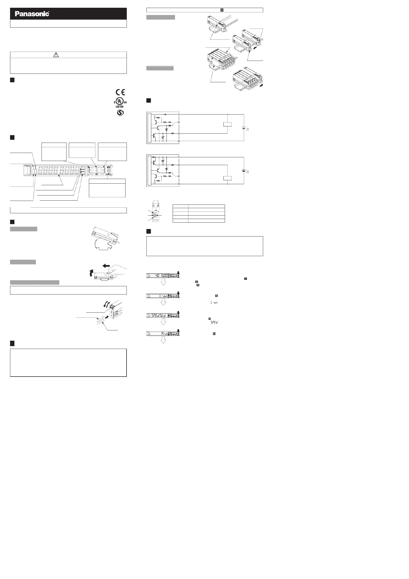
INSTRUCTION MANUAL
Digital Fiber Sensor Amplier □FX-502
MJE-FX502 No.0015-33V
Thank you very much for purchasing Panasonic products.
Please read this Instruction Manual carefully and thoroughly for the correct and
optimum use of this product.
Kindly keep this manual in a convenient place for quick reference.
WARNING
●Never use this product as a sensing device for personnel protection.
●In case of using sensing devices for personnel protection, use products which
meet laws and standards, such as OSHA, ANSI or IEC etc., for personnel
protection applicable in each region or country.
1
INTENDED PRODUCTS FOR CE MARKING
●This product complies with the following standards / regulations.
<EU Directive>
EMC Directive 2004/108/EC
<Standards in US / Canada>
ANSI/UL 60947-5-2, CAN/CSA C22.2 No.14
<Regulations in Korea>
S1-G-1-2009, S2-W-5-2009
●Caution about UL recognition
In case requiring conformity of UL listing mark or C-UL listing mark, USe class
2 power supply unit.
2
PART DESCRIPTION
Pressing down SET key + MODE key for 3 sec: Set key lock or release key lock
3
MOUNTING
How to connect
1. Fit the rear part of the mounting sec-
tion of the amplier on a DIN rail.
2. Press down the rear part of the
mounting section of the unit on the
DIN rail and fit the front part of the
mounting section to the DIN rail.
How to remove
1.
Push the controller forward.
2. Lift up the front part of the amplier
to remove it.
How to connect the ber cable
Be sure to t the attachment to the bers rst before inserting the bers to the
amplier. For details, refer to the instruction manual enclosed with the bers.
1. Snap the fiber lock lever down till it
stops completely.
2. Insert the ber cables slowly into the
inlets until they stops. (Note)
3. Return the fiber lock lever to the
original position till it stops.
Note:
With the coaxial reective type ber, such as, FD-G4
or FD-FM2, insert the single core ber cable into the
beam-emitting inlet “P” and the multi-core ber cable
into the beam-receiving inlet. If they are inserted in
reverse, the sensing performance will deteriorate.
4
INSTALL MORE AMPLIFIER OF SERIES CONNECTION TYPE
●Make sure that the power supply is OFF while adding or removing the series connection type.
●In case 2 or more the series connection types are connected in cascade, make
sure to mount them on a DIN rail.
● 11 the series connection types using sub cables can be added to an amplier
using a main connection cable.
●When connecting 2 or more the series connection types in cascade, use the
sub cable (optional) for the second series connection type onwards.
<Reference>
Fiber lock lever
Fiber for
receiver
1. Snap
3. Return
2. Insert
Fiber for emitter
2. Lift up
1. Push forward
2. Press down
1. Fit
35mm width DIN rail
Digital display
(Green / Red)
UP key
• Teaching
• Threshold value
ne adjustment
• Select setting items
MODE key
• Select Modes
• Cancel during setting
• Select sensing output 1/2
by pressing long
SET key
• Teaching
• C o nfir m s etti n g
contents
DOWN key
• Teaching
• Threshold value ne
adjustment
• Select setting items
Sensing output 2
selection indicator
(Yellow)
Sensing output 1
selection indicator
(Yellow)
Sensing output 1
operation indicator
(Orange)
Sensing output 2
operation indicator
(Orange)
MODE indicator: CUST (Yellow)
MODE indicator: PRO (Yellow)
MODE indicator: L / D (Yellow)
For mounting and removing the amplier, refer to “ MOUNTING.”
How to cascade
1. Mount the ampliers, one by one,
on the DIN rail.
2. Slide the amplifiers next to each
ot her, and connect the quick-
connection cables.
3. Mount the end plates MS-DIN-E
(optional) at both the ends to hold
the amplifiers between their flat
sides.
4.
Tighten the screws to fix the end
plates.
How to Remove
1. Loosen the screws of the end
plates.
2. Remove the end plates.
3. Slide the amplifiers and remove
them one by one.
5
I/O CIRCUIT DIAGRAMS
<FX-502>
<FX-502P>
Note: The quick-connection sub cable does not incorporate +V (brown) and 0V (blue). The power is supplied from
the connector of the main cable.
<Terminal arrangement>
Terminal
No. Terminal name
1 +V
2 Sensing output 1
3 Sensing output 2 / External input
4 0V
6
OPERATION PROCEDURE
●The sensing output can be switched to sensing output 1 or sensing output 2
by holding down the mode key.
●The changed settings are not stored if turning the power OFF while setting.
Therefore, conrm the settings by pressing the SET key before turning the
power OFF.
●When turning ON the power, RUN mode is displayed and the digital display
shows the threshold value (green) and the incident light intensity (red).
• Displays threshold value (green) and incident light intensity (red).
• Teaching, threshold value ne adjustment and key lock function can be set.
• For setting method of each function, refer to “TEACHING
MODE,” “
THRESHOLD VALUE FINE ADJUSTMENT FUNC-
TION,” or “
KEY LOCK FUNCTION.”
<RUN mode>
• Select either Light-ON or Dark-ON.
• For the setting, refer to
“SENSING OUTPUT OPERATION
MODE
.”
• The default setting is “ ” (Light-ON).
<Sensing output operation mode>
• An item set in CUSTOM mode (Response time setting, Emission
power setting and Hysteresis setting) is displayed.
• For details, refer to “
CUSTOM MODE.”
• The default setting is “
” (response time setting).
<CUSTOM mode>
• Advanced setting can be done.
• For the setting, refer to “
PRO MODE.”
<PRO mode>
<RUN mode>
Load
+
-
12 to 24V DC
%
Main circuit
(Brown) +V (Note)
(Black) Sensing output 1
(White) Sensing output 2 / External input
(Blue) 0V (Note)
Main circuit
(Brown) +V (Note)
(Blue) 0V (Note)
(Black) Sensing output 1
(White) Sensing output 2 / External input
+
-
12 to 24V DC
%
Load
2
3
1
4
Slide
Communication
window
Slide
Main cable
(Optional)
Sub cable
(Optional)
End plate
MS-DIN-E (Optional)
End plate
MS-DIN-E
(Optional)
Produktspezifikationen
| Marke: | Panasonic |
| Kategorie: | Nicht kategorisiert |
| Modell: | FX-502 |
Brauchst du Hilfe?
Wenn Sie Hilfe mit Panasonic FX-502 benötigen, stellen Sie unten eine Frage und andere Benutzer werden Ihnen antworten
Bedienungsanleitung Nicht kategorisiert Panasonic

11 Januar 2026
22 Dezember 2025
21 Dezember 2025
9 November 2025
8 Oktober 2025
7 Oktober 2025
2 Oktober 2025
26 September 2025
18 September 2025
16 September 2025
Bedienungsanleitung Nicht kategorisiert
- SpyTec
- Heatit
- Comelit
- Drive Medical
- Karella
- Rome
- Pentair
- ZKTeco
- CAT
- Smeg
- Citronic
- Keenetic
- CHINT
- Yealink
- Akuvox
Neueste Bedienungsanleitung für -Kategorien-
20 Januar 2026
20 Januar 2026
20 Januar 2026
20 Januar 2026
20 Januar 2026
20 Januar 2026
20 Januar 2026
20 Januar 2026
20 Januar 2026
20 Januar 2026