Panduit VS-CKP4-000 Bedienungsanleitung


Lies die bedienungsanleitung für Panduit VS-CKP4-000 (4 Seiten) kostenlos online; sie gehört zur Kategorie Nicht kategorisiert. Dieses Handbuch wurde von 7 Personen als hilfreich bewertet und erhielt im Schnitt 4.9 Sterne aus 4 Bewertungen. Hast du eine Frage zu Panduit VS-CKP4-000 oder möchtest du andere Nutzer dieses Produkts befragen? Stelle eine Frage

Seite 1/4
VeriSafe Insulation-Piercing
Connect Kit ion s
Insulation-Piercing Connectors for
VeriSafe AVT Sensor Lead Tapping on Copper Conductors
T-PMPI-322EN
Rev. 03 [12-2019]
INSTALLATION INSTRUCTIONS
Models: VS-CKP14-6, VS-CKP4-000
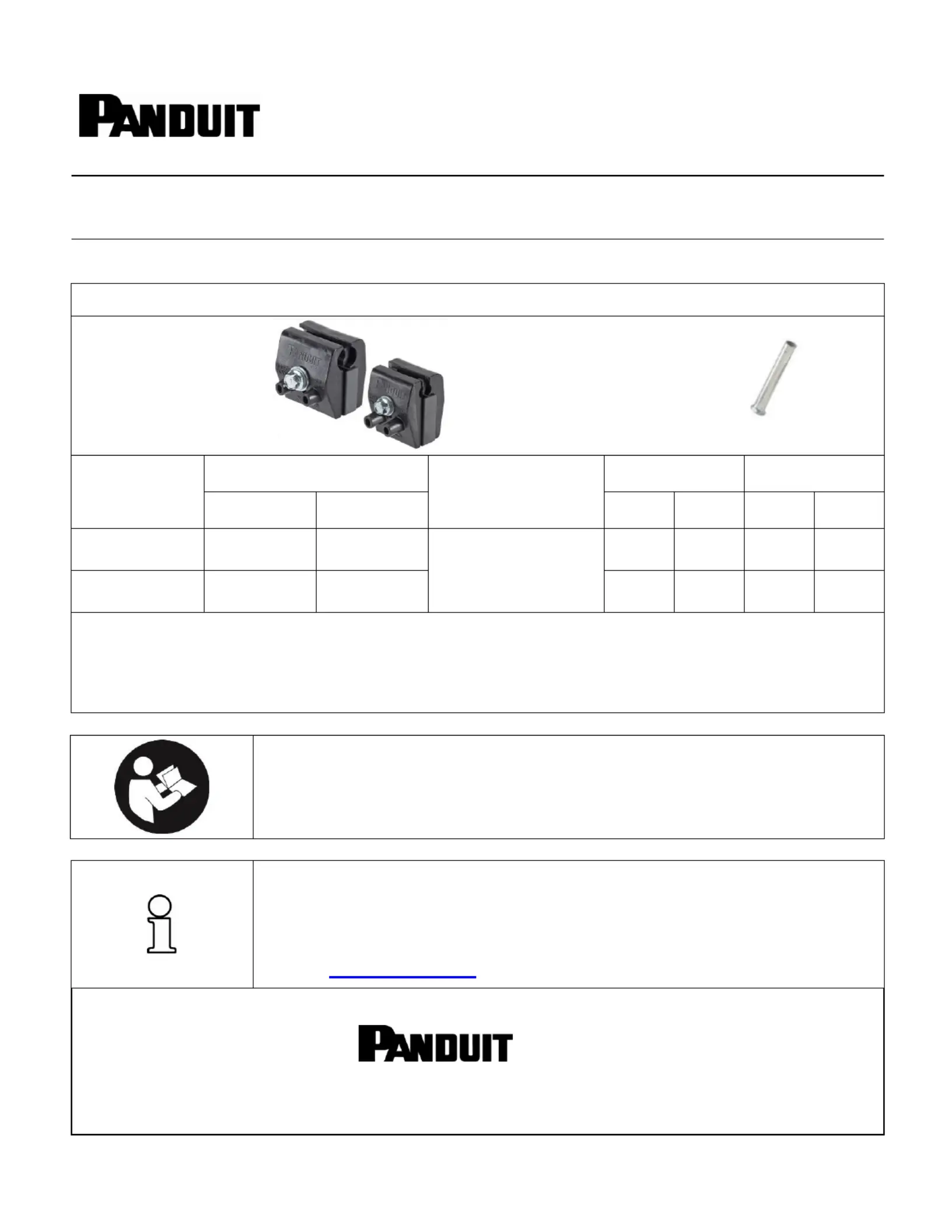
Connection Kit Contents: contains connectors and ferrules for installation of VeriSafe AVT
Panduit VSC Series
Insulation-Piercing
Connectors
+
Panduit
F80-12
Ferrules
CONNECTION
KIT CATALOG
PART NUMBER
“RUN” Wire
(CODE WIRE)
“TAP” Wire AWG
(Terminated w/ Ferrule)
CONNECTOR
FERRULE
MIN. AWG
[METRIC, mm2]
MAX. G AW
[METRIC, mm2]
Catalog
P/N
Quantity
Catalog
P/N
Quantity
VS-CKP14-6
14 AWG
[2.1, r]
6 AWG
[13.3, r]
14 AWG STR
Class K
(Terminated w/ Ferrule)
VSC6
3
F80- 12
12
VS-CKP4- 000
4 AWG
[21.2, r]
3/0 AWG STR
[85, r]
VSC3/0
3
F80- 12
12
IMPORTANT:
M install Ferrules Tap Wires fore terminating Tap Wires into Panduit Connector. ust on be VSC
Terminate Tap Wires into Panduit VSC Connector before installing Connector on a Phase Wire.
Read Page 2; contains Safety Information and operating limits for Connector per product listing.
TO REDUCE THE RISK OF INJURY, USER
MUST READ INSTALLATION INSTRUCTIONS
BEFORE ATTEMPTING TO INSTALL
NOTE: In the interest of higher quality and value, Panduit products are
continually being improved and updated. Consequently, pictures
may vary from the enclosed product.
NOTE: Updates to this Installation Instructions may be available. Check
www.panduit.com for the latest version of this manual.
Email:
techsupport@panduit.com
EU Website:
www.panduit.com/emea
EU Email:
emeatoolservicecenter
@panduit.com
www.panduit.com
Panduit Corp.
USA Technical Support
Tel: 800-777-3300
Panduit Europe • EMEA Service Center
Tel: +31 546 580 452 • Fax: +31 546 580 441
© Panduit Corp. 20 18
INSTALLATION INSTRUCTIONS
Models: VS-CKP14-6, VS-CKP4-000
T-PMPI-322EN
Rev. 03 [12-2019]
DOC# T-PMPI-322EN Page Rev 03 [12-2019]: 2of 4
Safety Information
This installation instructions contains information and warnings which must be followed to ensure safe
termination and operation of the Insulation-piercing Connectors and an AVT Device.
Always de-energize panel and verify absence of voltage in the panel before attempting to install
connector. Do not install connector on an energized conductor.
Installer must also follow all AVT safety, installation, commissioning and operating steps from
the AVT Device Manual.
Connector is intended for one-time installation and use. Do not reuse nor re-install connector.
Connector Ratings Information
(1) Panduit VSC Series
Insulation-Piercing
Connectors are intended for
simplifying installation and
connection of PANDUIT
VeriSafe AVT Absence of
Voltage Testers to phase
(run) conductors.
(2) Panduit VSC Series
Insulation-Piercing
Connectors must be used
within the rated ating oper
environment and installed
according to the Listed
product ratings in this Table
Panduit CATALOG P/N (VSC Connector)
VSC6
VSC3/0
MAX. Operating Temperature (° C)
90°C
MAX. Operating Voltage (Volts)
600V
RUN
WIRE
Torque-driver SAE Hex Size
(Main Fastener)
5 /16”
3/8”
Installation Torque (Required)
40 in- lb
[4.52 N m]
80 in- lb
[9.04 N m]
Minimum Rated Wire Size, AWG
[Metric, mm2, rigid]
14 SOL
14 STR
[2.1, r]
4 SOL
4 STR
[21.2, r]
Maximum Rated Wire Size, AWG
[Metric, mm2, rigid]
6 SOL
6 STR
[ , r] 13.3
3/0 STR
[85, r]
TAP
WIRE
Torque-driver Installation Bit Size
T10 Torx
Torque-driver Installation Tool
( ) recommended
Wiha P/N 28502
Installation Torque (Required)
7 in- lb
[0.79 N m]
Listed
Tap Wire Ferrule and
Combinations
[Tap Wire Size/Type
a nd
Panduit Ferrule P/N]
#1
TAP Wire
14 AWG STR Class K
F80- 12 ferrule
Ferrule
#2
TAP Wire
16 AWG STR Class K
F - ferrule 78 12
Ferrule
#3
TAP Wire
18 AWG STR Class K
F76- ferrule 12
Ferrule
Recommended Crimp Tool (Panduit P/N)
CT- 1160
Overview of Installation Process (Connector)
Before proceeding fer to the simplied ow-chart below, which indicates the steps taken for each , re
connector ring installation Understand these steps before proceeding further with illustrated details. du .
WIRE
CONNECTOR
587H
Plan AVT
Sensor Lead
Routing and
Trim Length of
Sensor Leads
Strip insulation
on Sensor Leads
to proper length
for each Ferrule
Crimp
Ferrules
on he t
Sensor
Leads
Fully-insert crimped
wires into Connector
and tighten terminal
screw to specied
torque (tap wire)
Position Connector
onto Phase Wire
and tighten the
Main Fastener to
specied torque
0
1
2
3
11
12
13
© Panduit Corp. 20 18
INSTALLATION INSTRUCTIONS
Models: VS-CKP14-6, VS-CKP4-000
T-PMPI-322EN
Rev. 03 [12-2019]
DOC# T-PMPI-322EN Page Rev 03 [12-2019]: 3of 4
Step- -Step Installation Procedure by
Step- -step illustrated instructions for installation are as follows;by
STEPS 1 thru Prepare Sensor ( e FIGURE 1) 3: Leads se
1. Prepare (strip) AVT device sensor leads.
2. Crimp ferrules onto sensor leads.
3. Make locating mark on sensor leads.
STEP 4: Review Connector Features (see FIGURE 2 and FIGURE ) 2*
STEP 5: Loosen factory-tightened MAIN FASTENER (see FIGURE 2)
STEP 6(a): Review Connector Features (see FIGURES 3 and 4)
STEP 6(b): Remove TAP TORQUE Reminder Lab (see FIGURES 3 and 4)el
Inspect location of factory-tightened TERMINAL in each TAP WIRE port in connector.
Each TERMINAL SCREW and
TERMINAL was shipped in a
factory-tightened state.
In a factory-tightened state, the
TERMINAL blocks access to and
restricts insertion of TAP WIRE.
Installer must loosen TERMINAL
SCREW and push down to ensure
TERMINAL position permits
insertion of TAP WIRE.
REMOVE TAP TORQUE reminder
label before proceeding to STEP 7.
FIGURE 1
0.875”
FERRULE (see Page 2)
[Connector Rating Table] s
STRIP
SENSOR LEAD
INSULATION
AFTER PROPER TERMINATION OF FERRULE,
MARK LINE ON CONDUCTOR INSULATION
FROM END OF CRIMPED FERRULE
TERMINAL
POSITION
RESTRICTS
INSERTION
OF TAP
WIRE
FIGURE 3
(TERMINAL Position)
FIGURE 4
(Detail View)
COMPLETELY REMOVE TAP TORQUE LABEL
FROM CONNECTOR BEFORE STEP 7
FIGURE 2*
FIGURE 2
TAP WIRE INSERTION PORTS
ARE FOR INSERTING A PAIR OF
COLOR-CODED, CRIMPED AND
FULLY-INSERTED TAP WIRES
(AVT SENSOR LEADS) INTO THE
CONNECTOR TERMINALS
TERMINAL SCREWS ARE
ACCESSIBLE FROM THE TWO
PORTS. TERMINAL SCREWS
ADJUST THE CONNECTOR
TERMINALS CONNECTOR .
TERMINALS ARE USED TO
TERMINATE TAP WIRES (AVT
SENSOR LEADS) IN CONNECTOR
MAIN
FASTENER
*Note: Connector may feature integrated Wire
Management Protrusions for optional use.
After Tap Wires are terminated into Connector,
(after Installation ep 11) the Protrusions can St
be used restrain Tap Wires near Connector to
using cable ties or other acceptable methods.
Wire Management Protrusions
Apply Cable
Ties after
Step 11


Produktspezifikationen

Marke: Panduit
Kategorie: Nicht kategorisiert
Modell: VS-CKP4-000

Brauchst du Hilfe?

Wenn Sie Hilfe mit Panduit VS-CKP4-000 benötigen, stellen Sie unten eine Frage und andere Benutzer werden Ihnen antworten