PCE Instruments PCE-DPD-F1 Bedienungsanleitung
PCE Instruments
Messung
PCE-DPD-F1
Lies die bedienungsanleitung für PCE Instruments PCE-DPD-F1 (16 Seiten) kostenlos online; sie gehört zur Kategorie Messung. Dieses Handbuch wurde von 9 Personen als hilfreich bewertet und erhielt im Schnitt 4.4 Sterne aus 5 Bewertungen. Hast du eine Frage zu PCE Instruments PCE-DPD-F1 oder möchtest du andere Nutzer dieses Produkts befragen? Stelle eine Frage
Seite 1/16

Output and control opons
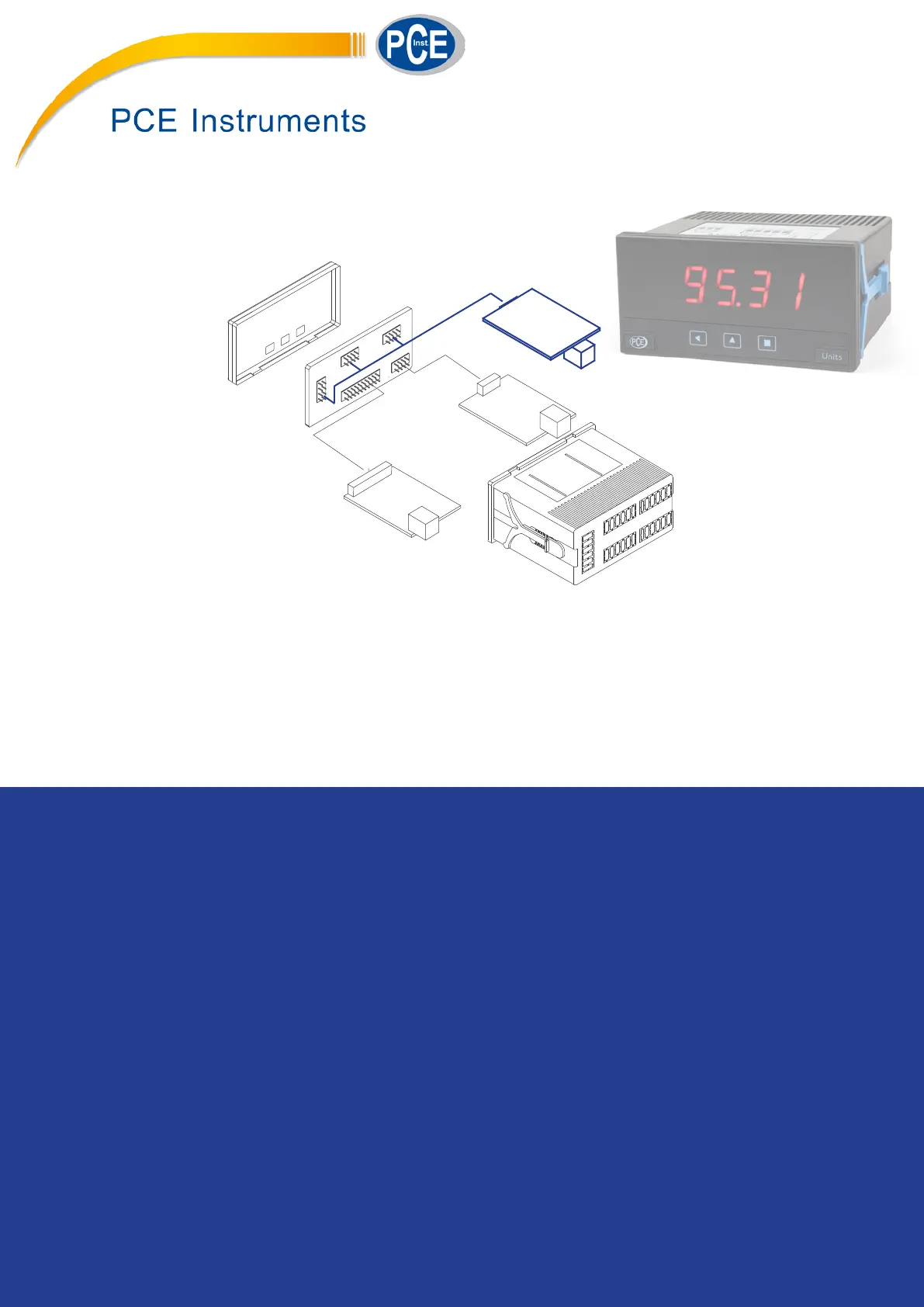
DIGITAL PANEL METERS
Modular output and control opons for panel meters from series PCE-DPD (except PCE-DPD-U). Relay
outputs, transistor outputs, SSR control outputs, analog outputs, Modbus RTU communicaons, RS-
485 and RS-232 communicaons.
PANEL METERS . OUTPUT AND CONTROL OPTIONS
4908E
www.pce-instruments.com

2
PCE Instruments PCE Instruments | www.pce-instruments.com
Index
1.1 Read this rst . . . . . . . . . . . . . . . . . . . . . . . . 2
1.2 Modular architecture. . . . . . . . . . . . . . . . . . . . 2
1.3 Installaon and start-up . . . . . . . . . . . . . . . . . . 2
1.4 To open the housing . . . . . . . . . . . . . . . . . . . . 3
1.5 Internal modules . . . . . . . . . . . . . . . . . . . . . . 3
1. Opons PCE-DPD/R, PCE-DPD/T and PCE-DPD/SSR . . . . . 4
2. Opon PCE-DPD/AV . . . . . . . . . . . . . . . . . . . . . . 5
2.1 Conguraon menu . . . . . . . . . . . . . . . . . . . . 6
2.2 Error codes . . . . . . . . . . . . . . . . . . . . . . . . . 6
3. Opon PCE-DPD/
MB . . . . . . . . . . . . . . . . . . . . . . . .7
3.1 Accessible registers. . . . . . . . . . . . . . . . . . . . . 7
3.2 Conguraon menu . . . . . . . . . . . . . . . . . . . . 8
3.3 Excepon codes. . . . . . . . . . . . . . . . . . . . . . . 8
3.4 Descripon and example of registers . . . . . . . . . . . 9
4. Opon PCE-DPD/485. . . . . . . . . . . . . . . . . . . . . . 10
4.1 Accessible registers. . . . . . . . . . . . . . . . . . . . . 10
4.2 Conguraon menu . . . . . . . . . . . . . . . . . . . . 11
4.3 Frame types . . . . . . . . . . . . . . . . . . . . . . . . . 12
4.4 Frame structure. . . . . . . . . . . . . . . . . . . . . . . 12
4.5 Error codes . . . . . . . . . . . . . . . . . . . . . . . . . 12
4.7 Frame examples . . . . . . . . . . . . . . . . . . . . . . 13
4.7.1 Frames ‘RD’ (36) and ‘ANS’ (37) . . . . . . . . . . . .13
4.7.2 Frames ‘ERR’ (38) . . . . . . . . . . . . . . . . . . . .13
4.7.3 Frames ‘PING’ (32) and ‘PONG’ (33). . . . . . . . . . 13
4.6 CRC calculaon . . . . . . . . . . . . . . . . . . . . . . .13
5. Opon PCE-DPD/232. . . . . . . . . . . . . . . . . . . . . . 14
All modules menoned in this document are compable with digital
panel meters PCE-DPD series (except mulinput panel meter PCE-
DPD-U). Dierent series dier in the number of digits, the digit height
and the number of output and control opons they can accept.
The output and control modules menoned in this document, are
covered by the warranty of the instrument where they are installed.
Check the user’s manual of the instrument for more informaon re-
lated to warranty.
The user’s manual of the instrument where the module is
installed, has important informaon related to installaon
that applies also to the output and control modules men-
oned in this document. Check the user’s manual of the
instrument for more informaon related to installaon precauons.
The output and control modules menoned in this docu-
ment are covered by the ‘CE declaraon of conformity’ of
the instrument where they are installed. Check the user’s
manual of the instrument for more informaon related to
the CE declaraon of conformity.
1.1 Read this rst
Digital panel meters from series M, K and S are designed following a
modular architecture that allows the operator to install any od the
output and control modules menoned in this document.
1.2 Modular architecture
1.3 Installaon and start-up
To install an oponal output and control module into a digital panel
meter from series PCE-DPD:
1. open the housing of the instrument (see secon 1.4)
2. install the module at slot Opt.1’, ‘Opt.2’ or ‘Opt.3’ as preferred and
close the instrument
3. close the housing of the instrument (see secon 1.4)
4. if needed, congure the appropriate jumpers at the module
5. connect the signal output terminals
6. congure the parameters at the ‘Conguraon menu’.
• modules PCE-DPD/R, T1 and SSR are congured from the alarms
menu of the instrument where the module has been installed
• other modules are congured from its own conguraon menu,
accessible from menu entries ‘Opt.1’, ‘Opt.2’ or ‘Opt.3’, depending
on the slot where the module has been installed.
!
Produktspezifikationen
Marke: | PCE Instruments |
Kategorie: | Messung |
Modell: | PCE-DPD-F1 |
Brauchst du Hilfe?
Wenn Sie Hilfe mit PCE Instruments PCE-DPD-F1 benötigen, stellen Sie unten eine Frage und andere Benutzer werden Ihnen antworten
Bedienungsanleitung Messung PCE Instruments
25 Juli 2025
25 Juli 2025
25 Juli 2025
25 Juli 2025
25 Juli 2025
25 Juli 2025
25 Juli 2025
25 Juli 2025
Bedienungsanleitung Messung
- Beckmann & Egle
- CIRCUTOR
- ORNO
- X-Rite
- Oregon Scientific
- Westfalia
- TFA Dostmann
- Zircon
- Wetekom
- Endress+Hauser
- Smartwares
- Beha-Amprobe
- Testboy
- TDE Instruments
- AREXX
Neueste Bedienungsanleitung für -Kategorien-
31 Juli 2025
31 Juli 2025
31 Juli 2025
31 Juli 2025
31 Juli 2025
31 Juli 2025
31 Juli 2025
30 Juli 2025
29 Juli 2025
29 Juli 2025