PCE Instruments PCE-VT 204 Bedienungsanleitung
PCE Instruments Messgeräte PCE-VT 204
Lies die bedienungsanleitung für PCE Instruments PCE-VT 204 (36 Seiten) kostenlos online; sie gehört zur Kategorie Messgeräte. Dieses Handbuch wurde von 27 Personen als hilfreich bewertet und erhielt im Schnitt 4.6 Sterne aus 6 Bewertungen. Hast du eine Frage zu PCE Instruments PCE-VT 204 oder möchtest du andere Nutzer dieses Produkts befragen? Stelle eine Frage
Seite 1/36
Manual
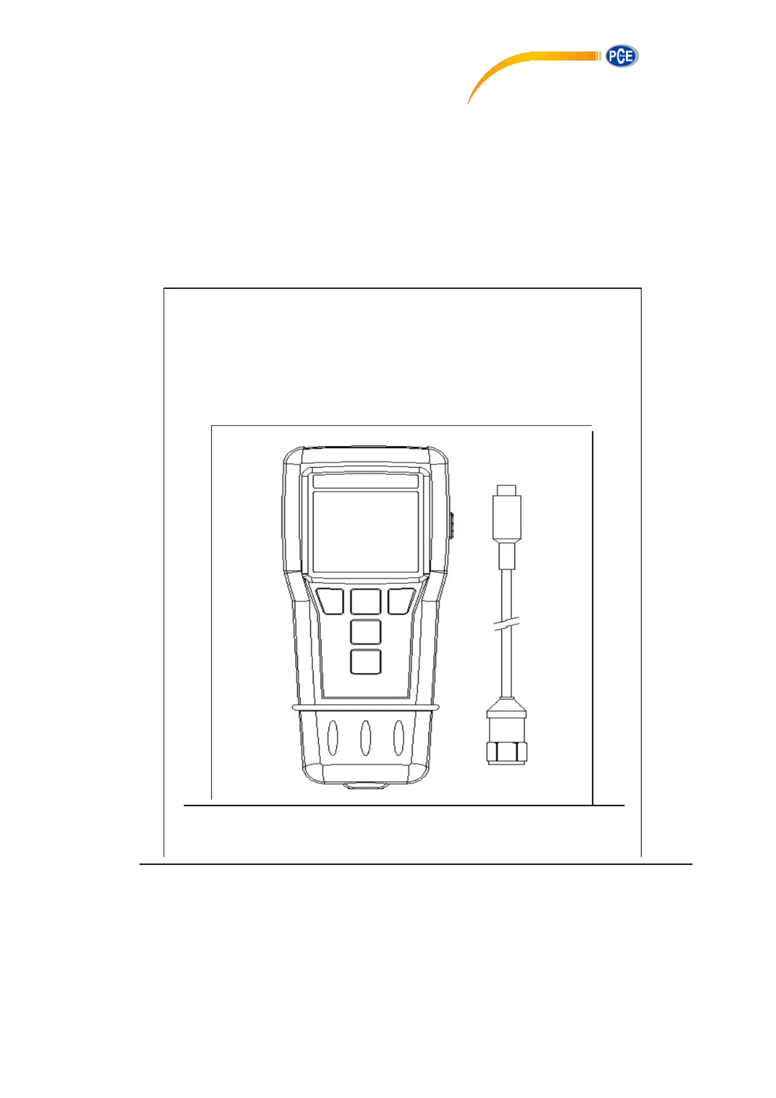
Vibration Analyser
PCE-VT 204
PCE Americas Inc.
711 Commerce Way
Suite 8
Jupiter
FL-33458
USA
From outside US: +1
Tel: (561) 320-9162
Fax: (561) 320-9176
www.pce-instruments.com/english
www.pce-instruments.com
PCE Instruments UK Ltd.
Units 12/13
Southpoint Business Park
Ensign way
Hampshire / Southampton
United Kingdom, SO31 4RF
From outside UK: +44
Tel: (0) 2380 98703 0
Fax: (0) 2380 98703 9
Produktspezifikationen
| Marke: | PCE Instruments |
| Kategorie: | Messgeräte |
| Modell: | PCE-VT 204 |
Brauchst du Hilfe?
Wenn Sie Hilfe mit PCE Instruments PCE-VT 204 benötigen, stellen Sie unten eine Frage und andere Benutzer werden Ihnen antworten
Bedienungsanleitung Messgeräte PCE Instruments

16 Oktober 2024
16 Oktober 2024
16 Oktober 2024
16 Oktober 2024
16 Oktober 2024
16 Oktober 2024
16 Oktober 2024
16 Oktober 2024
16 Oktober 2024
16 Oktober 2024
Bedienungsanleitung Messgeräte
Neueste Bedienungsanleitung für -Kategorien-
16 Oktober 2024
16 Oktober 2024
15 Oktober 2024
15 Oktober 2024
15 Oktober 2024
15 Oktober 2024
15 Oktober 2024
15 Oktober 2024
15 Oktober 2024
15 Oktober 2024