Scanstrut Flip Pro Multi SC-MULTI-F1 Bedienungsanleitung
Scanstrut Nicht kategorisiert Flip Pro Multi SC-MULTI-F1
Lies die bedienungsanleitung für Scanstrut Flip Pro Multi SC-MULTI-F1 (2 Seiten) kostenlos online; sie gehört zur Kategorie Nicht kategorisiert. Dieses Handbuch wurde von 15 Personen als hilfreich bewertet und erhielt im Schnitt 4.6 Sterne aus 9 Bewertungen. Hast du eine Frage zu Scanstrut Flip Pro Multi SC-MULTI-F1 oder möchtest du andere Nutzer dieses Produkts befragen? Stelle eine Frage
Seite 1/2
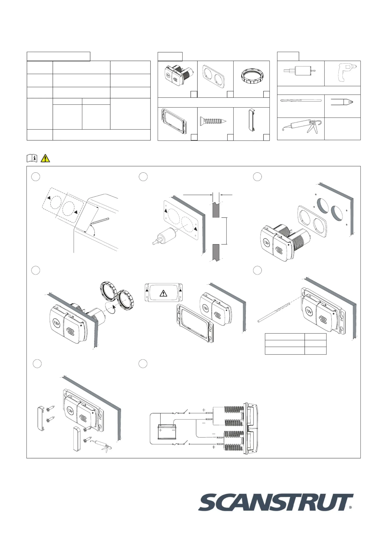
FLIP PRO MAX-DUAL USB-C & 12V POWER SOCKET
(SC-MULTI-F1)
17-05-2023 (Issue 2)
Installation Instructions
For further installation
and warranty information
please visit:
www.scanstrut.com
USA
+1 860 308 1416
UK & International
+44 (0)1392531280
Draw a centre line to align template,
ensure line is square on surface and
correct orientation.
90°
TOP
1
Use drilling template to drill x2 Ø32mm
(1 1/4”) holes (see tools required).
Ø32mm
(1.25”)
3mm (0.11”) Min
25mm (1”) Max
2
Feed Barrel through the gasket and
holes.
3
4
6
7
REAR INSTALL ONLY
Tighten lock rings onto product until
FRONT INSTALL ONLY
Push bezel onto the product, make sure
FRONT INSTALL ONLY
Apply silicone seal on xings and pilot
holes.
Connect to 12V supply, ensuring a waterproof
connection. Fuse and select cable diameter
according to input voltage and current for your
specic installation.
** If using a 24V system a voltage converter is
required on the 12V socket only**
Pilot Hole Size
Material No. 6 Screw
Soft Material e.g Plywood2.5mm (3/32”)
Hard Material e.g Fiberglass3mm (1/8”)
FRONT INSTALL ONLY
Drill 4 pilot holes for bezel.
5
TOP
32mm (1 1/4”) Hole sawDrill
Front install only
Drill bit 2.5mm (3/32”) or
3mm (1/8”)Pozi Screwdriver
Silicone
Tool list:
2 Socket & USB
ChargerGasketLock Ring
Front install only
Front Fit Bezel
No.6x20mm
ScrewsScrew Cover
Parts list:
x1x1
x1
x4
x2
x2
For latest tech info visit: www.scanstrut.com/USB
READ IMPORTANT SAFETY
INFORMATION BEFORE INSTALLING.
Technical information:
USB Charger12V Socket
Input
voltage
12/24V System
10-32V DC
12V System
10-15V DC
Input
current Max
6 A10 A
Output Type
(12V System) (24V System)
12V10A⎓
5V3A, ⎓
9V3A, ⎓
12V3A MAX⎓
5V3A, ⎓
9V3A, ⎓
12V3A, ⎓
15V3A, ⎓
20V3A MAX⎓
Standby
draw
< 0.1W
Produktspezifikationen
| Marke: | Scanstrut |
| Kategorie: | Nicht kategorisiert |
| Modell: | Flip Pro Multi SC-MULTI-F1 |
Brauchst du Hilfe?
Wenn Sie Hilfe mit Scanstrut Flip Pro Multi SC-MULTI-F1 benötigen, stellen Sie unten eine Frage und andere Benutzer werden Ihnen antworten
Bedienungsanleitung Nicht kategorisiert Scanstrut

28 August 2025
27 August 2025
27 August 2025
27 August 2025
27 August 2025
27 August 2025
27 August 2025
27 August 2025
1 August 2025
1 August 2025
Bedienungsanleitung Nicht kategorisiert
Neueste Bedienungsanleitung für -Kategorien-
1 April 2026
1 April 2026
1 April 2026
1 April 2026
1 April 2026
1 April 2026
1 April 2026
1 April 2026
1 April 2026