Supermicro SuperBlade SBI-4119MG-X Bedienungsanleitung
Supermicro Server SuperBlade SBI-4119MG-X
Lies die bedienungsanleitung für Supermicro SuperBlade SBI-4119MG-X (1 Seiten) kostenlos online; sie gehört zur Kategorie Server. Dieses Handbuch wurde von 19 Personen als hilfreich bewertet und erhielt im Schnitt 4.5 Sterne aus 10 Bewertungen. Hast du eine Frage zu Supermicro SuperBlade SBI-4119MG-X oder möchtest du andere Nutzer dieses Produkts befragen? Stelle eine Frage
Seite 1/1
S
UPERMICR
R
ContaCtnformatIonI
•Manuals: http://www.supermicro.com/support/manuals
•Drivers & Utilities:
https://www.supermicro.com/wftp/driver/
•Safety: http://www.supermicro.com/about/policies/safety_information.cfm
© 2019 Supermicro Computer Inc. All rights reserved. Reproduction of this document whether in part or in whole is strictly prohibited without Supermicro's written
consent. All Trademarks are property of their respective entities. All information provided is deemed accurate at the time of printing; however, it is not guaranteed.
B11SCG-CTF/ZTF
Quick Reference Guide 1.00
•Website: www.supermicro.com
•General Information: marketing@supermicro.com
•Technical Support: support@supermicro.com
•Phone: +1 (408) 503-8000, Fax: +1 (408) 503-8008
F oryoursystemtoworkproperlypleasedownloadappropriate,
driversimagesusersmanualFromthelinksbelow//' :
MNL-2187-QRG-100
WARNING: This product can expose you to chemicals including
lead, known to the State of California to cause cancer and birth
defects or other reproductive harm. For more information, go
to www.P65Warnings.ca.gov.
!
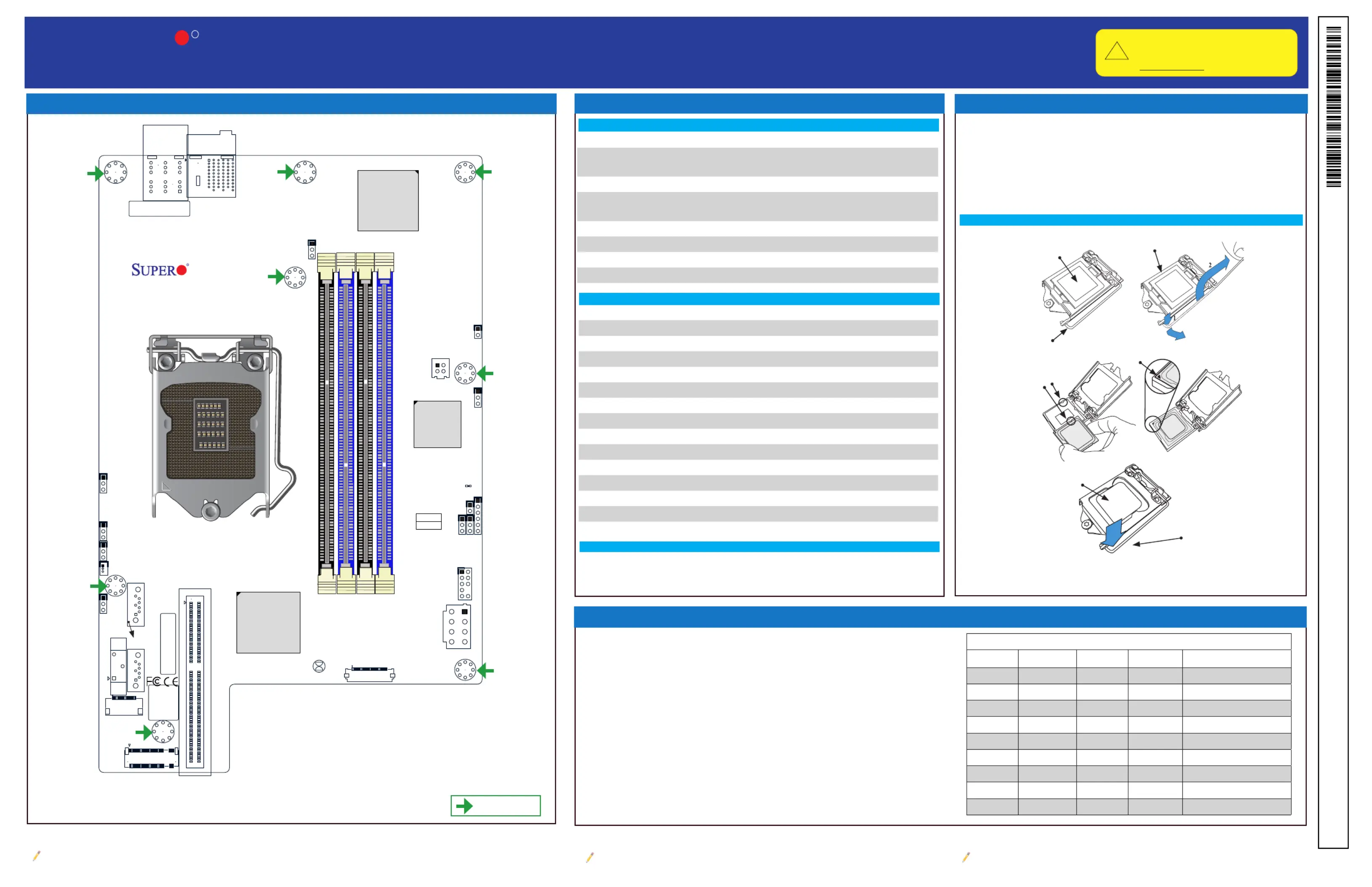
Jumpers
Jumpers, Connectors and LED Indicators
Memory Support and Installation
Note: Graphics shown in this quick reference guide are for illustration only. Your components may or may not look exactly the same as drawings shown in this
guide.
Note: Refer to Chapter 1 of the User Manual for detailed information on jumpers, connectors,
and LED indicators.
Note: Refer to Chapter 2 of the User Manual for detailed information on memory support and CPU/
motherboard installation instructions.
CPU Support and Installation
The B11SCG-CTF supports up to 128GB of ECC UDIMM memory with speeds up to
2666MHz.
The B11SCG-ZTF supports up to 64GB of DDR4 Non-ECC UDIMM memory with speeds
of up to 2666MHz.
See below for additional memory information.
• The blue slots must be populated rst.
• Always use DDR4 memory of the same type, size, and speed. Mixed DIMM speeds
can be installed. However, all DIMMs will run at the speed of the slowest DIMM.
• The motherboard will support odd-numbered modules.However, to achieve the best
memory performance, a balanced memory population is recommended.
The B11SCG-CTF motherboard supports the Intel® Xeon® E-2100 processor or
an 8th/9th Generation Intel Core i3/Pentium®/Celeron® processors in a LGA 1151
(H4) socket.
The B11SCG-ZTF supports an 8th/9th generation Intel Core i7/i5/i3/Pentium/
Celeron processors in an LGA1151 (H4) socket.
ConnectorDescription
BT1Onboard CMOS Battery
I-SATA4/I-SATA3Intel® PCH SATA 3.0 Ports
J4CPLD Programming Header (Manufacturing Use Only)
JDBG1VRM Debug Jumper (Manufacturing Use Only)
JFP1Front Panel Cable Connector
JKVM1VGA/USB Module Connector
JPO1Power Button Bypass (Manufacturing Use Only)
JPWR212V GPU Card Power Connector
JPWR34-pin Power Connector for SATA/SAS
JSD1SATA DOM Power Connectors
JTPM1Trusted Platform Module (TPM)/Port 80 Connector
JVR1VRM Programming Header (Manufacturing Use Only)
M.2-HM.2 Slot
PWR1Power Receptable to Chassis Backplane
MAC CODE
BAR CODE
BIOS LICENSE
7
1
DESIGNED IN USA
B11SCG-CTF/ZTF
REV:1.01
BT1
JPWR3
JBT1
MH1
MH3
MH5
MH7
MH8
JPWR2
I-SATA3I-SATA4
PWR1
JKVM1
BMC_HB_LED1
JTPM1
JSD1
JDBG1
J2
J5
JPG1
JPME1
JWD1
JVR1
JPME2
JBR1
JPO1
JFP1
MH2
MH6
MH4
J4
M.2-H
PCIE 3.0 x16
CPU
JPG1:
1-2:ENABLE
2-3:DISABLE
JPTM1:TPM/PORT80
JPO1:
2-3:DISABLE
1-2:ENABLE
JSD1:SATA DOM POWER
JPME2:
1-2:NORMAL
2-3:ME MANUFACTURING MODE
VGA
JWD1:WATCH DOG
2-3:NMI
1-2:RES
JPME1:
1-2:NORMAL
2-3:ME RECOVERY
CMOS
CLEAR
JBR1:
1-2:NORMAL
2-3:BIOS RECOVERY
DIMMA2
DIMMA1
DIMMB1
DIMMB2
X710
PCH
C246/Z370
BMC
AST2500
DIMMA1
DIMMA2
DIMMB1
DIMMB2
LED Indicators
LEDDescriptionStatus
BMC_HB_LED1BMC Heartbeat LEDGREEN Blinking: Normal
= mounting hole
Load Plate
JumperDescriptionDefault Setting
J5PCIe Expansion Option
Pins 1-2 (x8 Slot1/x8 Slot
2 or p1-x16 Slot1)
JBR1BIOS RecoveryPins 1-2 (Normal)
JBT1Clear CMOSShort: Clear CMOS
Open: Normal
JPG1VGA Enable/DisablePins 1-2 (Enabled)
JPME1ME Recovery Pins 1-2 (Normal)
JPME2Manufacturing Mode SelectPins 1-2 (Normal)
JWD1Watch Dog EnablePins 1-2 (Reset)
Connectors
CPU Properly
Installed
Load Lever Locked
into Place
Load Lever
Plastic Protective
Cover
Motherboard Layout and Features
Load Plate
CPU / Socket
Keys
Lift Lever
and Remove
Protective
Cover
Pin 1
CPU Installation
Recommended Population (Balanced)
DIMMA1DIMMB1DIMMA2DIMMB2Total System Memory
4GB4GB8GB
4GB4GB4GB4GB16GB
8GB8GB16GB
8GB8GB8GB8GB32GB
16GB16GB32GB
16GB16GB16GB16GB64GB
32GB32GB64GB
32GB32GB32GB96GB
32GB32GB32GB32GB128GB
Produktspezifikationen
| Marke: | Supermicro |
| Kategorie: | Server |
| Modell: | SuperBlade SBI-4119MG-X |
Brauchst du Hilfe?
Wenn Sie Hilfe mit Supermicro SuperBlade SBI-4119MG-X benötigen, stellen Sie unten eine Frage und andere Benutzer werden Ihnen antworten
Bedienungsanleitung Server Supermicro

21 Januar 2026
14 November 2025
Supermicro SuperServer E403-9D-14CN-FRDN13+ Bedienungsanleitung
21 Oktober 2025 21 Oktober 2025
21 Oktober 2025
13 Oktober 2025
10 Oktober 2025
9 Oktober 2025
9 Oktober 2025
9 Oktober 2025
Bedienungsanleitung Server
Neueste Bedienungsanleitung für -Kategorien-
20 Januar 2026
20 Januar 2026
16 Januar 2026
29 Dezember 2026
28 Dezember 2025
16 Dezember 2025
10 Dezember 2025
6 Dezember 2025
5 November 2025
4 November 2025