Supermicro SuperServer 6029TP-HC1R Bedienungsanleitung
Supermicro Server SuperServer 6029TP-HC1R
Lies die bedienungsanleitung für Supermicro SuperServer 6029TP-HC1R (5 Seiten) kostenlos online; sie gehört zur Kategorie Server. Dieses Handbuch wurde von 22 Personen als hilfreich bewertet und erhielt im Schnitt 4.9 Sterne aus 11.5 Bewertungen. Hast du eine Frage zu Supermicro SuperServer 6029TP-HC1R oder möchtest du andere Nutzer dieses Produkts befragen? Stelle eine Frage
Seite 1/5
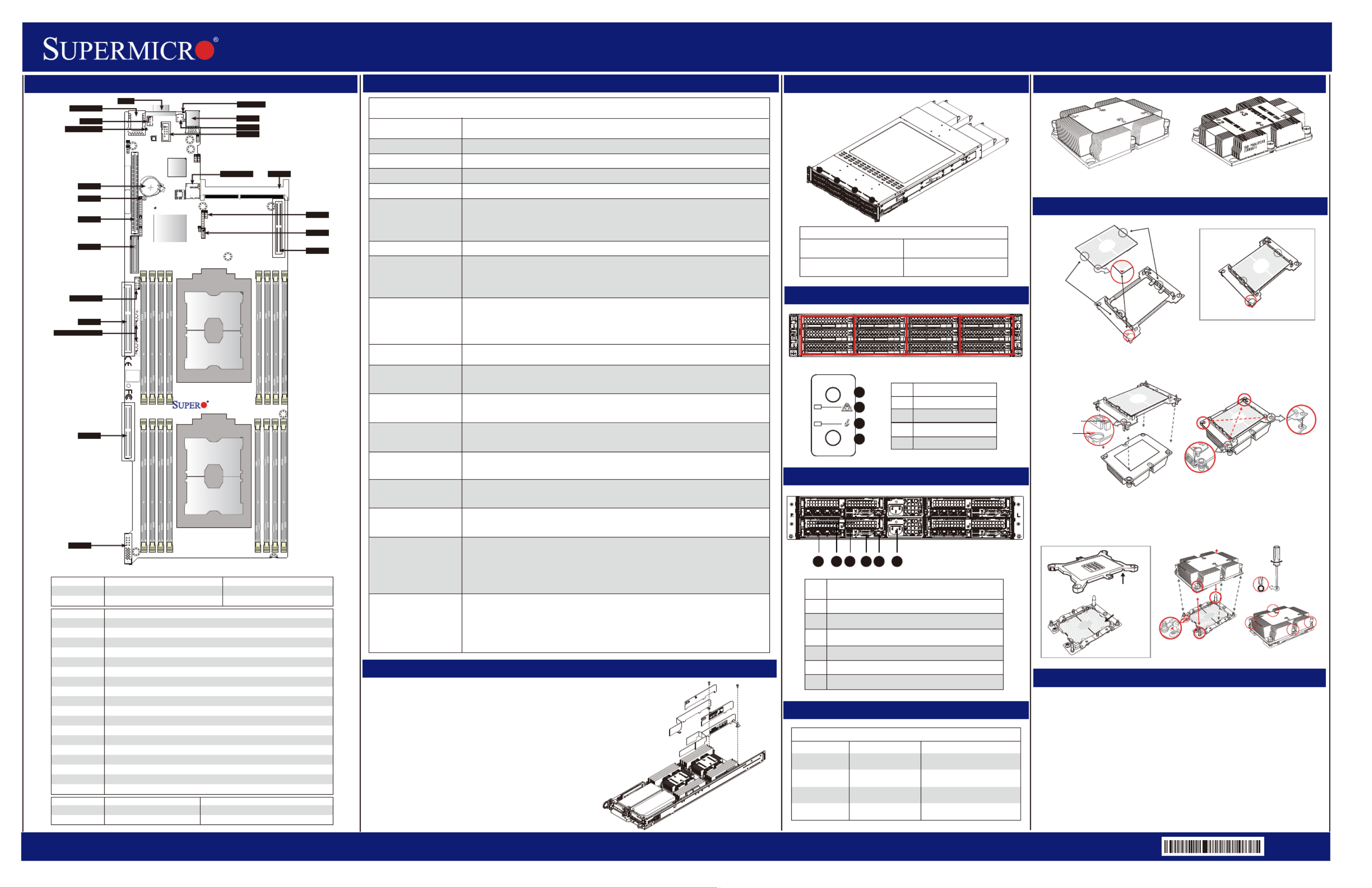
SuperServer 6029TP-HTR/-HC1R/-HC0R Quick Reference Guide
http://www.supermicro.comMNL-1963-QRG Rev 1.0b
Description
No.
1
2
3
4
5
6
2 PCI-E 3.0 p1-x16 Slots
VGA Port
IPMI_dedicated LAN Port
2 USB 3.0 Ports
SIOM Slot
Power Supply Module
1624 35
Jumpertnt SgDescripioDefaulettin
JBTpen(Normal1OCMOS Clear )
JPin1-2 (NormalME1PManufacturing Mode Selects )
CortnonnectDescrip io
BT1Onboard battery
COM 1COM port (COM1) on the I/O backplane
FAN 3System cooling fan header
IP_LMIAN Dedicated IPMI LAN port (IPMI_LAN1)
I-SATA4/I-SATA5Intel® PCH SATA3.0 ports with power-pin built-in w/support of SuperDOM (Device-On Module)
JHS1SMCI-Proprietary Power supply header
JRK1RAID_Key for onboard SATA devices
JSDCARD1BMC_SD card header
JSIOM1Super I/O Module used as CPU1 PCI-E 3.0 p1-x16 slot
JTPM1Trusted Platform Module/Port 80 connector
JUIDB1UID (Unit Identifier) switch
SXB1 (for S-SATA 0-5)PCI-E 3.0 p1-x8 slot supported by CPU1 for use of S-SATA 0-5 devices
SXB2 (for I-SATA 0-3)PCI-E 3.0 p1-x16 slot supported by CPU2 for use of I-SATA 0-3 devices
SXB3_1PCI-E 3.0 p1-x16 slot supported by CPU1
SXB3_2PCI-E 3.0 p1-x8 slot supported by CPU2
SXB4PCI-E 3.0 p1-x16 slot supported by CPU2
USB0/1Backplane Universal Serial Bus (USB) 3.0 ports 0/1
VGAVGA Port
LEipioDDescrtnSe: Statustat
BBEDB tt LEDMC_H_LMCHear beaBlinking Green: BMC Normal
UID_LED1UID (Unit Identifier) LEDSolid Blue: Unit Identified
P5 S20
S1
BIOS
LICENSE
MAC CODE
BAR CODE
P1-DIMMF1
P1-DIMME1
P1-DIMMD1
P1-DIMMD2
P2-DIMMC1
P2-DIMMB1
P2-DIMMA1
P2-DIMMA2
P2-DIMMD2
P2-DIMMD1
P2-DIMME1
P2-DIMMF1
P4
SXB3_2
JCPLD1
PHY
HDD_LED
I-SATA0~3
S-SATA0~5
CPU1 PCI-E 3.0 X16
CPU2 PCI-E 3.0 X8
CPU1 PCI-E 3.0 X8
CPU2 PCI-E 3.0 X16
BATTERY
BIOS
BMC
BMC SD CARD
SIOM:CPU1 PCI-E 3.0 X16
CPU1
CPU2 PCI-E 3.0 X16
P1-DIMMA2
P1-DIMMA1
P1-DIMMB1
P1-DIMMC1
CPU2
X11DPT-PS
Rev. 1.10
JVRM1/JVRM2
PCH
JWD1
JBT1
SXB1
SXB2
SXB3_1
SXB3_2
JHS1
BT1
JSIOM1
FAN3
BMC_HB_LED
IPMI_LAN
JTPM1
JUIDB1
JSDCARD1
VGA UID_LED1
I-SATA4/I-SATA5
COM1
USB0/1
JPME1
JRK1
SXB4
Board Layout
Air Shroud installation
Installing the Air Shroud
1. Lay the chassis on a flat, stable surface and remove the chassis cover.
2. Make sure that the motherboard expansion card (if applicable) and all
components are properly installed in each motherboard node.
3. If necessary, move any cables that interfere with the air shroud placement.
4. Place the air shroud in the chassis. The air shroud fits just behind the three
fans in the fan rack. Slide the air shroud into the grooves just behind the fan rack.
5. Repeat the procedure for the remaining three motherboard nodes.
6. Reroute any cables that were moved and replace the chassis cover.
Memory Support
Memory Population Table
When 1 CPU is used
Memory Population Sequence
1 CPU & 1 DIMMCPU1: P1-DIMMA1
1 CPU & 2 DIMMsCPU1: P1-DIMMA1/P1-DIMMD1
1 CPU & 3 DIMMs CPU1: P1-DIMMC1/P1-DIMMB1/P1-DIMMA1
1 CPU & 4 DIMMsCPU1: P1-DIMMB1/P1-DIMMA1/P1-DIMMD1/P1-DIMME1
CPU1: P1-DIMMC1/P1-DIMMB1/P1-DIMMA1/P1-DIMMD1/P1-DIMME1
1 CPU & 6 DIMM
1 CPU & 5 DIMMs
(Unbalanced: not
recommended)
CPU1: P1-DIMMC1/P1-DIMMB1/P1-DIMMA1/P1-DIMMD1/P1-DIMME1/P1-DIMMF1
1 CPU & 7 DIMMs
(Unbalanced: not
recommended)
CPU1:P1-DIMMC1/P1-DIMMB1/P1-DIMMA1/P1-DIMMA2/P1-DIMMD1/P1-DIMME1/
P1-DIMMF1
1 CPU & 8 DIMMs
(Unbalanced: not
recommended)
CPU1: P1-DIMMC1/P1-DIMMB1/P1-DIMMA1/P1-DIMMA2/P1-DIMMD2/P1-DIMMD1/
P1-DIMME1/P1-DIMMF1
Memory Population Sequence
When 2 CPUs are used
2 CPUs & 2 DIMMsCPU1: P1-DIMMA1
CPU2: P2-DIMMA1
2 CPUs & 4 DIMMsCPU1: P1-DIMMA1/P1-DIMMD1
CPU2: P2-DIMMA1/P2-DIMMD1
2 CPUs & 6 DIMMsCPU1: P1-DIMMC1/P1-DIMMB1/P1-DIMMA1
CPU2: P2-DIMMC1/P2-DIMMB1/P2-DIMMA1
2 CPUs & 8 DIMMsCPU1: P1-DIMMB1/P1-DIMMA1/P1-DIMMD1/P1-DIMME1
CPU2: P2-DIMMB1/P2-DIMMA1/P2-DIMMD1/P2-DIMME1
2 CPUs & 10 DIMMsCPU1: P1-DIMMC1/P1-DIMMB1/P1-DIMMA1/P1-DIMMD1/P1-DIMME1/P1-DIMMF1
CPU2: P2-DIMMB1/P2-DIMMA1/P2-DIMMD1/P2-DIMME1
2 CPUs & 12 DIMMsCPU1: P1-DIMMC1/P1-DIMMB1/P1-DIMMA1/P1-DIMMD1/P1-DIMME1/P1-DIMMF1
CPU2: P2-DIMMC1/P2-DIMMB1/P2-DIMMA1/P2-DIMMD1/P2-DIMME1/P2-DIMMF1
2 CPUs & 14 DIMMs
(Unbalanced: not
recommended)
CPU1: P1-DIMMC1/P1-DIMMB1/P1-DIMMA1/P1-DIMMA2/P1-DIMMD1/P1-DIMME1/
P1-DIMMF1
CPU2: P2-DIMMC1/P2-DIMMB1/P2-DIMMA1/P2-DIMMA2/P2-DIMMD1/P2-DIMME1/
P2-DIMMF1
2 CPUs & 16 DIMMs
(Unbalanced: not
recommended)
CPU1: P1-DIMMC1/P1-DIMMB1/P1-DIMMA1/P1-DIMMA2/P1-DIMMD2/P1-DIMMD1/
P1-DIMME1/P1-DIMMF1
CPU2: P2-DIMMC1/P2-DIMMB1/P2-DIMMA1/P2-DIMMA2/P2-DIMMD2/P2-DIMMD1/
P2-DIMME1/P2-DIMMF1
Heatsinks
Caution
SAFETY INFORMATION
IMPORTANT: See installation instructions and safety warning before
connecting system to power supply.
http://www.supermicro.com/about/policies/safety_information.cfm
WARNING:
To reduce risk of electric shock/damage to equipment, disconnect power
from server by disconnecting all power cords from electrical outlets.
If any CPU socket empty, install protective plastic CPU cap
WARNING:
Always be sure all power supplies for this system have the same power
output. If mixed power supplies are installed, the system will not operate.
For more information go to : http://www.supermicro.com/support
!
!
!
Heatsink SNK-P0067PSM
(for CPU2)
Heatsink SNK-P0067PS
(for CPU1)
CPU Installation
Processor Carrier Assembly (with CPU mounted
on the Processor Clip)
CPU (Upside Down)
w/CPU LGA Lands up
On Locations of (C, D), the notches
snap onto the heat sink’s
mounting holes
On Locations (A, B), the notches
snap onto the heatsink’s sides
Heatsink
(Upside Down)
CPU and Processor Clip
Attaching the Processor Carrier Assembly to the Heatsink to Form the Processor
Heatsink Module (PHM)
Removing the Dust Cover from
the CPU Socket
Installing the Processor Heatsink Module (PHM)
Dust Cover
CPU Socket
Remove the dust cover from the CPU socket, exposing the
socket and socket pins as shown on the illustration below.
No: te
Do not touch the socket pins to avoid damaging
them, causing the CPU to malfunction.
Note:Do not use excessive force when tightening the screws to avoid
damaging the LGA lands and the processor.
Mounting the Processor Heatsink Module into
the CPU socket (on the motherboard)
Align Notch C of the
CPU and Notch C of
the Processor Clip
CPU/Heatsink Package
(Upside Down)
Align Notch B of the
CPU and Notch B of
the Processor ClipA
B
C
Allow carrier to
latch onto CPU
Allow carrier to
latch onto CPU
Processor Carrier Assembly
B
C
B
C
Pin 1
A
A
Align CPU Pin 1
Socket Pins
Remove the plastic protective
cover from the CPU socket.
Do not touch or bend
the socket pins.
Triangle on the CPU
Triangle on the
Processor Carrier
a
b
A
B
d
c
D
C
Make sure Mounting
Notches snap into place
A
B
D
C
Small Guiding Post
Oval C (Large Guiding Post)
Printed Triangle
12
3
4
T30 Torx Driver
Use a torque of 12lbf-in
Oval D
Tighten the screws in the
sequence of 1, 2, 3, 4 (top 3 quarter view)
Drives Controled by Nodes
Rear View
BIOS Error Beep (POST) Codes
Beep CodeError MessageDescription
1 shortRefreshCircuits have been reset (Ready
to power up)
System overheat condition
5 short, 1 longMemory Error
5 long, 2 shortDisplay memory read/
write error
Beep Codes
Front view & InterfaceFront view & Interface
No memory detected in the
system
1 long continuousSystem OH
Video adapter missing or with
faulty memory
Description
No.
1
2
3
4
Power
NIC
Information LED
UID
POWER
UID
Node ANode BNode CNode D
Motherboard B controls HDDs
B0, B1, B2, B3, B4, and B5
Motherboard A controls HDDs
A0, A1, A2, A3, A4, and A5
Motherboard D controls HDDs
D0, D1, D2, D3, D4, and D5
Motherboard C controls HDDs
C0, C1, C2, C3, C4, and C5
1
2
3
4
Nodes and Corresponding Hard Drives
S AB:
S BB:
SB: C
SB: D
A
D
C
B
Air Shroud Components
Produktspezifikationen
| Marke: | Supermicro |
| Kategorie: | Server |
| Modell: | SuperServer 6029TP-HC1R |
Brauchst du Hilfe?
Wenn Sie Hilfe mit Supermicro SuperServer 6029TP-HC1R benötigen, stellen Sie unten eine Frage und andere Benutzer werden Ihnen antworten
Bedienungsanleitung Server Supermicro

21 Januar 2026
14 November 2025
Supermicro SuperServer E403-9D-14CN-FRDN13+ Bedienungsanleitung
21 Oktober 2025 21 Oktober 2025
21 Oktober 2025
13 Oktober 2025
10 Oktober 2025
9 Oktober 2025
9 Oktober 2025
9 Oktober 2025
Bedienungsanleitung Server
Neueste Bedienungsanleitung für -Kategorien-
20 Januar 2026
20 Januar 2026
16 Januar 2026
29 Dezember 2026
28 Dezember 2025
16 Dezember 2025
10 Dezember 2025
6 Dezember 2025
5 November 2025
4 November 2025