Supermicro SuperServer SYS-512B-WR Bedienungsanleitung
Supermicro Server SuperServer SYS-512B-WR
Lies die bedienungsanleitung für Supermicro SuperServer SYS-512B-WR (1 Seiten) kostenlos online; sie gehört zur Kategorie Server. Dieses Handbuch wurde von 29 Personen als hilfreich bewertet und erhielt im Schnitt 5.0 Sterne aus 15 Bewertungen. Hast du eine Frage zu Supermicro SuperServer SYS-512B-WR oder möchtest du andere Nutzer dieses Produkts befragen? Stelle eine Frage
Seite 1/1
+
JNVME2
DESIGNED IN USA
SAN MAC
MAC CODE
REV:1.01
X14SBW-TF
IPMI CODE
BIOS LICENSE
BAR CODE
JSXB1A
JUIDB1
LED6
LAN1LAN2
LEDBMC
JNCSI
BMC_LAN
USB0/1 (3.0)
COM1
MH2
JPL3
JPL2
JPL1
JMP1
JMP2
COM2
LED4
JM2_1JM2_2
LED7
MH13
MH12
MH10
MH11
JDB2
JPRG1
JPFR3
JPFR2
JDB3
JPT1
JBT1
BT1
JSXB2: PCIe 5.0 p1-x8 (in x16)
JSXB1B: PCIe 5.0 p1-x16 + x16
USB2/3
JF1
LEDPWR
JNVME4
JTMED
MH1
VGA
JTPM1
JVRM1
JVRM2
JSYSID2
JSYSID1
JNVME1
MH8
JPI2C1
JRK1
JSTBY1
JDB1
JPWR3
JPWR1JPWR2
MH7
FAN1FAN2
FAN3
MH5
FAN4
FAN5
FAN6
JL1
JNVME3
JIPMB1
MH9
JBPNI2C1JSEN1
JNVI2C1
SATA0–7
JSXB1C
MH6
MH15
DIMME1
DIMMF1
DIMMG1
DIMMH1
DIMMD1
DIMMC1
DIMMB1
DIMMA1
http://www.supermicro.comMNL-2687-QRGRev. 1.0
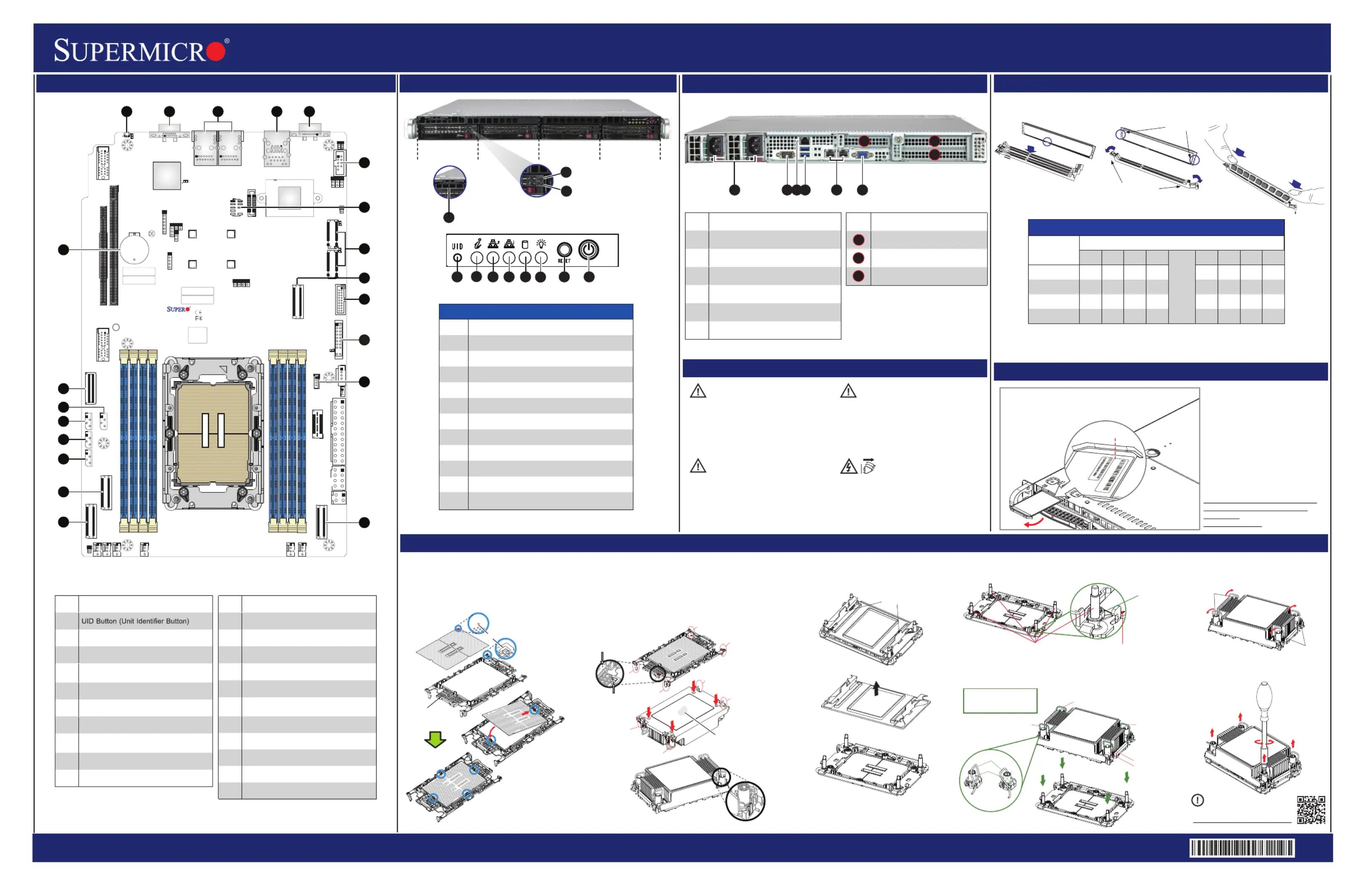
SuperServer 512B-WR Quick Reference Guide
Caution
Board Layout
Rear View and Features
Front View and Features
BMC Password Label
Memory
CPU Installation, supporting a single Intel® Xeon® 6 Processor (LGA 4710)
12
6
7
5
8
3
For mofo: re inrmation go to
ht:tp//www.upo.sermcricom/srtuppo
PRODUCT RESOURCES:
B. Assembling the Processor Heatsink Module (PHM)
1. If this is a new heatsink, the thermal grease has been preapplied. Otherwise, apply the proper
amount of thermal grease.
2. Hold the processor carrier assembly so the processor's gold contacts are facing up, then align
the holes of the processor carrier assembly with the holes on the heatsink. Press the processor
carrier assembly down until it snaps into place. The plastic clips of the processor carrier assembly
will lock at the four corners.
3. Examine all corners to ensure that the plastic clips on the processor carrier assembly are firmly
attached to the heatsink.
Pin 1
a
c
b
d
A
C
B
D
A. Creating the Intel Xeon 6 CPU Carrier Assembly
1. Locate small gold triangle (Pin 1) on processor and corresponding
hollowed triangle on carrier.
2. Using the triangles as a guide, carefully align and place Point A of
the processor into the carrier. Gently snap into place to fasten onto
Point B.
Pin 1
Make sure the lever
is pressed down before
installing the processor.
A
B
Processor Carrier Assembly
(Upside Down)
Check each corner to ensure that the processor carrier is firmly attached to the heatsink.
Triangle on the
processor carrier
Triangle on the CPU
Thermal grease
C. Preparing the CPU Socket for Installation
Gently pull off the plastic protective cover by one corner to
remove it from the CPU socket.
D. Installing the Process Heatsink Module
1. Locate four threaded fasteners (a, b, c, d) on the CPU socket.3. Press all four rotating wires outward to latch the PHM
onto the CPU socket.
4. With a t30-bit screwdriver, tighten all PEEK nuts in the
sequence of A, B, C, and D with even pressure not greater
than 8 in-lbf (0.904 N-m).
A, B, C, D: Peek Nut
1, 2, 3, 4: Rotating Wire
a, b, c, d: Threaded Fastener
Peek Nut
(Unlatched)
(Latched)
Rotating Wire
a
c
b
d
C
A
D
B
Rotating Wire 1
Rotating Wire 3
Rotating Wire 4
Rotating Wire 2
Peek Nut
Grabsip T
a
b
c
d
(a, b, c, d: Threaded Fasteners)
CPU Socket Pin1
Threaded
Fenerast
CPU etSock
Rotating
Wire
Rotating
Wire
2. Locate four PEEK nuts (A, B, C, D) and four rotating wires (1, 2, 3, 4) on the heatsink as
shown below. Gently place the heatsink on the CPU socket, making sure that each nut is
properly aligned with its corresponding threaded fastener.
A
B
C
D
1
2
34
6
758
HDD 0HDD 1HDD 2HDD 3
CAUTION:
Always be sure all power supplies for this
system have the same power output.
If mixed power supplies are installed,
the systemwill not operate.
IMPORTANT: See installation instructions
and safety warning before connecting
system to power supply.
http://www.supermicro.com/about/policies/
safety_information.cfm
SAFETY INFORMATION:
To reduce risk of electric shock/damage to
equipment, disconnect power from server by
disconnecting all power cords from electrical
outlets. If any CPU socket empty, install
protective plastic CPU cap.
WARNING:
CAUTION:
This unit has redundant power sources.
Please disconnect all the power
cords before servicing.
Press Both Notches
Straight Down to the in
Mery Slotmo
Notches
Release Tabs
DIMMnstallation I
Est th aach syem comeswi
uniquedeaulpasword ft s for
theAIN us. DMer
T arhiscanbe foundon sticke
on the motherboard and a sticker
undeneaheeragrth t svice t on
cis.hass
If necesarys, the s npaswordca
beresebyheupermicr t t So
IPMIC.FG tool
For more information,
please visit
hpc/tts://.swwwupermiroom.c
enoluionmanagemen/sts/t-
so/ftware
bm-reourcsces
PULL
Pull-out tag with BMC unique
password and Serial Number
Label underneath.
BMC: XXXXXXXXXXXX
PWD: AMBWODMRGT
S/N: S123456XXX0123
S/N Label
11
9
10
4
9
10
11
12
13
16
14
17
15
21
20
19
18
DI eMMPopulionatGuid
Type
Chael nn
H1G1F1E1
CPU
A1B1C1D1
1 DIMM
V
2 DIsMM
VV
4 DIsMM
VVVV
8 DIsMM
VVVVVVVV
No te:Please refer to user manual for memory module [rank] and [DRAM density] requirements
when using Intel® Xeon® 6 CPU.
ItemtnDescripio
1t P S sRedundanowerupplyModule
2S Pterialor
3t B LAN PtDedicaedMCor
4Twoen1or U 3.2 GSB Pts
5LAN 1 LAN 2 Pts(left)and(right)or
6A PtVGor
Imt tnteSloDescripio
PCIe 5.0 x St (FH, . L)16lo123”
PCIe 5.0 x St (FH, . L)16lo123”
PCIe 5.0 x8 St P)(inx16)lo(L
246531
1
2
3
1
2
3
Item
1
Description
Control Panel Features
2
UID Button
3
Information LED
4
NIC2 LED
5
NIC1 LED
6
HDD LED
7
Power LED
8
Reset Button
9
Power Button
10
Drive Activity LED
11
Drive Status LED
Servicel/Asset Tag (pull-out identifier with
BMC ADMIN default password underneath)
ImtnteDescripio
1
2A PtVGor
3Twoor 1GbE LAN Pts
4
U 3.2 G 1 P / cat LAN SBenortsDedied
f MIorIP
5COM Pt (S Pt)orerialor
6COM Pt (S Pt)orHeadererialor
7: M rJM1TPTPHeade
8
JM2_1JM2_/2: M.2 PCIe 5.0 Interface
(M-2280and22key 110)
9: P 5.0 x8 orJNVME1CleMCIOConnect
10: U 3.2 G rUS/3B2SBen1Heade
ImtnteDescripio
11: Ft t P rJF1ronConrolanelHeade
12: Int VROC RD Key rJRK1elAIHeade
13: P x8 orJNVME2Cle5.0MCIOConnect
14: P 5.0 x8 orJNVME3CleMCIOConnect
15: P 5.0 x8 orJNVME4CleMCIOConnect
16
JMI1IP: t Bus SystemManagemen
Headeroronl (f MI IPy)
17: N I rJBPNI12CBP2CHeade
18: It Ss rJN1SEnleenorHeade
19: NV I rJN2CVI1Me2CHeade
20: S SA 3.0 PtsSA 7AT0-limSASATor
21O BaynboardCMOStter
Produktspezifikationen
| Marke: | Supermicro |
| Kategorie: | Server |
| Modell: | SuperServer SYS-512B-WR |
Brauchst du Hilfe?
Wenn Sie Hilfe mit Supermicro SuperServer SYS-512B-WR benötigen, stellen Sie unten eine Frage und andere Benutzer werden Ihnen antworten
Bedienungsanleitung Server Supermicro

14 November 2025
Supermicro SuperServer E403-9D-14CN-FRDN13+ Bedienungsanleitung
21 Oktober 2025 21 Oktober 2025
21 Oktober 2025
13 Oktober 2025
10 Oktober 2025
9 Oktober 2025
9 Oktober 2025
9 Oktober 2025
9 Oktober 2025
Bedienungsanleitung Server
Neueste Bedienungsanleitung für -Kategorien-
20 Januar 2026
20 Januar 2026
16 Januar 2026
29 Dezember 2026
28 Dezember 2025
16 Dezember 2025
10 Dezember 2025
6 Dezember 2025
5 November 2025
4 November 2025