TOA HY-CM20W Bedienungsanleitung
TOA Lautsprecher HY-CM20W
Lies die bedienungsanleitung für TOA HY-CM20W (1 Seiten) kostenlos online; sie gehört zur Kategorie Lautsprecher. Dieses Handbuch wurde von 7 Personen als hilfreich bewertet und erhielt im Schnitt 4.9 Sterne aus 8 Bewertungen. Hast du eine Frage zu TOA HY-CM20W oder möchtest du andere Nutzer dieses Produkts befragen? Stelle eine Frage
Seite 1/1
133-01-00122-00
15°
(30°)
45°
45°
[HY-CM20B, HY-CM20W]
Adjustable within this angle range.
The figure above is an example
of F-1000 series installation.
[HY-CM10B, HY-CM10W]
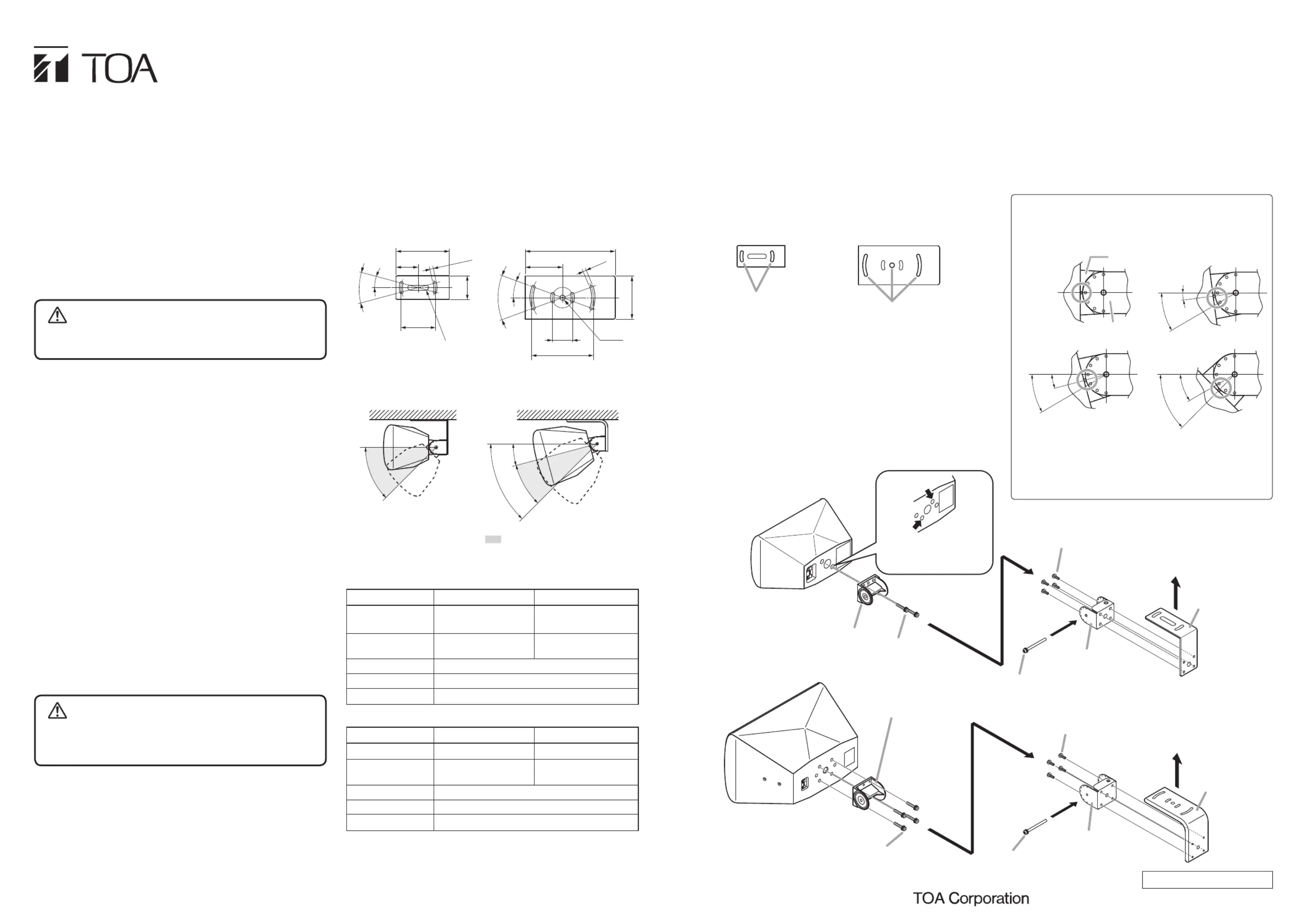
Unit: mm
9.8 x 41.8 oval hole
[HY-CM20B, HY-CM20W][HY-CM10B, HY-CM10W]
175
72.5
6.3
6.3
ø40ø9.8
84
40°
20°
30°
15°
ø120
108
45
ø70
48
Tip:The wall bracket supplied with each speaker is not used.
Step 1.h the r ct to the r of the sr Attacspeakebrakereapeake
cabinet. Use the screws supplied with the speaker.
(HY-CM10B/W: 2 pieces; HY-CM20B/W: 4 pieces)
Note: Mount the bracket so that the speaker is suspended
in a horizontal orientation.
Step 2.Ach a t ket to e cg t et g ttajoinbractheilinmounbrackusin
the supplied 4 screws.
Step 3.h the cg t t to the g usg the Attaceilinmounbrackeceilinin
ceiling mounting holes.
Note
Hardware used for mounting the ceiling mount bracket to
the ceiling is not supplied.
Step 4.Mount the speaker to the joint bracket.
It the r t to the t ct d nserspeakebrackeinjoinbrakean
looelsecurixinbolemporarspeakesy e the fg t for ty r
installation.
Step 5.Connect the speaker cable to the speaker input terminal.
For connections, refer to the instruction manual enclosed
with the speaker.
5.2. HY-CM20B and HY-CM20W
INSTALLATION MANUAL
CEILING MOUNT BRACKETS
HY-CM10B
HY-CM10W
HY-CM20B
HY-CM20W
3. MOUNTING DIMENSIONS
Step 6.At the sk's vtl tg e d tten djuspeaerericamouninanglanigh
the fixing bolt.
The speaker angle can be adjusted in 7.5º steps within the
range as follows.
• When the HY-10B/W is used
F-1000 series: 0º(horizontal) to 45º downward
F-1300 series: 7.5º to 45º downward
• When the HY
-20B/W is used
F-2000 series: 15º to 45º downward
•re n or , be re to ry rd l e Befoinstallatiousesucaefulleaalth
instructions in this section for correct and safe operation.
•Be sure to follow all the precautionary instructions in this section,
whiconaiimporanwarningandauionregardinch tn tt s /or cts g
safety.
•After reading, keep this manual handy for future reference.
1. SAFETY PRECAUTIONS
Indiatepotentiallhazadousituatiowhichcs a y rs n , if
mishandled, could result in death or serious personal injury.
WARNING
•Install the unit only in a location that can structurally support the
weight of the unit and the speaker. Doing otherwise may result in
the sker fg n d g l iy /or peaallindowancausinpersonanjurand
property damage.
•Sce the t is sd for r use, do t l it inunideigneindoonoinalst
outdooinstalleoutdoothaginpacausethrs. If d rs, e g of rts s e
speaker to fall off, resulting in personal injury.
•Do t e otr s n d to t the . noushemethodthaspecifiemoununit
Extreme force is applied to the unit and the speaker could fall off,
possibly resulting in personal injuries.
•Use nuts and bolts that are appropriate for the ceiling's structure
and composition. Failure to do so may cause the speaker to fall,
resulting in material damage and possible personal injury.
•Tighten each nut and bolt securely. Ensure that the unit has no
loe jots ar itlaon to ent is at ld osinftensaltiprevaccdentthcou
result in personal injury.
•Use the specified speaker
in combination. Doing otherwise may
cause the speaker to fall off, resulting in personal injury.
•Do not mount the unit in locations exposed to constant vibration.
Thunicadamagecesiibrationpotentialle t n be d by exsve v, y
causing the speaker to fall, which could result in personal injury.
•Do not use anti-rust lubricant. If it contacts resin or rubber parts,
ty d tte d se the t to f, sy hecouldeerioraancauuniallposibl
resulting in personal injury.
Indiatepotentiallhazadousituatiowhichcs a y rs n , if
mihandledcoulreulmoderaminopersonas, d st in te or r l
injury, and/or property damage.
CAUTION
•Avoid touching the unit's sharp metal edge to prevent injury.
•Do not hang down from the unit as this may cause it to fall down
or drop, resulting in personal injury and/or property damage.
•Have the unit checked periodically by the shop from where it was
purchased. Failure to do so may result in corrosion or damage to
the t tt d e the t to f, y g unihacoulcausuniallpossiblcausin
personal injury.
The HY-CM10B and HY-CM10W Ceiling Mount Brackets are used
to mount F-1000/1300 Series speakers to a ceiling in a horizontal
configuration.
T HYhe-CM20andB HY-CM20CeilingMounrackeareusedW t Bts
to moun-2000eriepeaerint F Ss sks a ztfhorional coniguraiont.
Note
To t the sker to the cg in a tical t, e mounpeaeilinverorientaionus
the brackets supplied with the speaker. For more information, refer
to the instruction manual enclosed with the speaker.
2. GENERAL DESCRIPTION
4. FINISHED ASSEMBLING DIAGRAM
5. SPECIFICATIONS
5.1. HY-CM10B and HY-CM10W
Note
The design and specifications are subject to change without notice
for improvement.
6. INSTALLATION
URL: http://www.toa.jp/
Speaker bracket
Joint bracket
45°
30°
30°
15°
Refer to the figures below for the positional relationship
between the speaker bracket's "groove" and the joint
bracket's "indentation."
Note
The mating surfaces of the speaker bracket and joint
bracket are designed to interlock.
Ensure that both parts are securely engaged with each
other after mounting is complete.
30°
7.5°
0°
(horizontal)
[0° (horizontal) position][7.5° downward position]
[15° downward position][45° downward position]
Mounting to the ceiling
HY-CM10B/W
HY-CM20B/W
• HY-CM20B, HY-CM20W
• HY-CM10B, HY-CM10W
Speaker bracket
(supplied with the speaker)
Speaker system
F-2000 series
Speaker bracket
(supplied with the speaker)
Screw M5 x 20
(supplied with the speaker)
Screw M5 x 20
(supplied with the speaker)
Joint bracket
(supplied with the speaker)
Accessory screw M5 x 10
2
4, 6
4, 6
Fixing bolt
(supplied with the speaker)
Fixing bolt
(supplied with the speaker)
Joint bracket
(supplied with the speaker)
Accessory screw M5 x 10
23
Mounting to the ceiling
3
1
1
Speaker system
F-1000 series
The figure above shows the
screw mounting positions
for the F-1300 series.
Ceiling mounting holes
(3 places)
[HY-CM20B, HY-CM20W][HY-CM10B, HY-CM10W]
Ceiling mounting holes
(2 places)
Models No.
HY-CM10B
HY-CM10W
Applicable Speaker
F-1000B, F-1000BT,
F-1300B, F-1300BT
F-1000W, F-1000WT,
F-1300W, F-1300WT
Finish
Steel plate, bck,la
paint
Steel plate, ite,wh
paint
Dimensions
48 (w) x 100 (h) x 108 (d) mm
Weight
210 g
Accessories
Machine screw M5 x 10 with washers …4
Models No.
HY-CM20B
HY-CM20W
Applicable Speaker
F-20B, F-20BT,F-20W,F-20WT,00000000
Finish
Steel plate, bck,la
paint
Steel plate, ite,wh
paint
Dimensions
84 (w) x 135 (h) x 175 (d) mm
Weight
610 g
Accessories
Machine rew M5 x 10 with washers …4sc
Produktspezifikationen
| Marke: | TOA |
| Kategorie: | Lautsprecher |
| Modell: | HY-CM20W |
| Breite: | 84 mm |
| Tiefe: | 175 mm |
| Gewicht: | 610 g |
| Produktfarbe: | Weiß |
| Material: | Stahl |
| Platzierung: | Ceiling, Wall |
| Höhe (max): | 135 mm |
Brauchst du Hilfe?
Wenn Sie Hilfe mit TOA HY-CM20W benötigen, stellen Sie unten eine Frage und andere Benutzer werden Ihnen antworten
Bedienungsanleitung Lautsprecher TOA

15 Oktober 2025
15 Oktober 2025
15 Oktober 2025
15 Oktober 2025
10 Oktober 2025
9 Oktober 2025
9 Oktober 2025
9 Oktober 2025
9 Oktober 2025
8 Oktober 2025
Bedienungsanleitung Lautsprecher
Neueste Bedienungsanleitung für -Kategorien-
3 April 2026
3 April 2026
3 April 2026
3 April 2026
2 April 2026
2 April 2026
2 April 2026
2 April 2026
2 April 2026
2 April 2026