Uni-T UT208 Bedienungsanleitung
Uni-T Messgeräte UT208
Lies die bedienungsanleitung für Uni-T UT208 (2 Seiten) kostenlos online; sie gehört zur Kategorie Messgeräte. Dieses Handbuch wurde von 49 Personen als hilfreich bewertet und erhielt im Schnitt 5.0 Sterne aus 4 Bewertungen. Hast du eine Frage zu Uni-T UT208 oder möchtest du andere Nutzer dieses Produkts befragen? Stelle eine Frage
Seite 1/2
Overview
This Operating Manual covers information on safety and cautions. Please read the
relevant information carefully and observe all the and strictly.Warnings Notes
Warning
To avoid electric shock or personal injury, read the “Safety Information”
carefully before using the Meter.
Model UT207 and UT208 are 3 5/6 digit AC&DC digital clamp multimeters
( hereafter referred to as "the Meter" ) characterized with stable performance, high
reliability and novel structure. They are designed with large-scale integrated circuits
and dual integral A/D converter as its core and offer full-range overload protection.
The Meter can measure AC/DC Voltage, AC/DC Current, Frequency, Duty Cycle,
Resistance, Diodes, Continuity, Surge Current and etc.
UT208 has an extra temperature feature.
Item Description Qty
1
2
3
4
5
English Operating Manual
Test Lead
PoinConact tt TemperaureProbenly208)hit (O UT (Ts
inludedpoinc t cta ttonctemperaureprobean c onlbeusey d
upto23 0
. Foranymeasurementishigherthanthat, the
rod type temperature probe must be used)
Tool box
9V Battery (NEDA1604A or 6LF22)
1 pc
1 pair
1 pair
1 pc
1 pc
Unpacking Inspection
OpenthepackagecaseandtakeouttheMete r. yCheckthefollowingitemscarefull
for any missing or damaged part:
Intheevent youfind anymissingor damaged part, please contact youdealerr
immediately.
Safety Information
This Meter complies with IEC61010-1, IEC61010-2-032, Pollution Degree 2,
Overvoltage Category(CAT.600V, CAT 300V) and Double Insulation standards.ⅡⅢ
CAT. , , PORTII:LocallevelapplianceABLEPMENwismaller EQUIT etc .,th transient
overvoltages than CAT. III.
CAT. t v, fix t, th r st ovets tnIII:Diibustrionleeledinallastionwismalletranienrvolageha
CAT. IV
Use the Meter only as specified in this operating manual, otherwise the protection
provided by the Meter may be impaired.
Inthmanua is l, aWgarniniifi iti and i dentescondonsactonsthatposhazardstoth e e
user, or may damage the Meter or the equipment under test.
A identifies the information that user should pay attention to.Note
To y, eavoidpossibleelectricshockorpersonalinjurandtoavoidpossibl
dge e Met or e e t a e gamatothertothquipntmeunderest,dheretothfollowin
rules:
Warning
Before using the Meter inspect the case. Do not use the Meter if it is
damaged or the case (or part of the case) is removed. Look for cracks or
missing plastic. Pay attention to the insulation around the connectors.
Inspectthetestleads fordamagedinsulationor exposedmetal.Checkth e
testea lds forconinuitty. dged lds th entil mel Reaceplamatesteawiidcaod
number or electrical specifications before using the Meter.
Donotapply morethanthe ratedvoltage,as markedonthe Meterbetwee , n
the terminals or between any terminal and grounding. If the value to be
measuredis unknown,use themaximummeasurement positionand reduce
the range step by step until a satisfactory reading is obtained.
When measurement has been completed, disconnect the connection between
the test leads and the circuit under test, remove the testing leads away
from the input terminals of the Meter and turn the Meter power off.
The rotary switch should be placed in the right position and no any
changeover of range shall be made during measurement toprevent
damage of the Meter.
Donotcarryoutthe measurementwhentheMeter’sback caseandbatter y
compartment are not closed to avoid electric shock.
Do not input higher than 600V between the two Meter’s input terminal to
avoid electric shock and damage to the Meter.
When the Meterworking at an effective voltage over 70V in DC or 33V rms is
in AC, special care should be taken for there is danger of electric shock.
Use the proper terminals, function, and range for your measurements.
Do not use or store the Meter in an environment of high temperature,
humidity, explosive,inflammable and strong magnetic field.The performance
of the Meter may deteriorate after dampened.
When using the test leads, keep your fingers behind the finger guards.
To avoid electric shock, do not touch the bare wires, connectors, unused
input terminals or the tested circuit during measurement.
Di cit a hge a ge pito borescectonnrcuipowernddiscarllhighol-vtacaacrsef
testing resistance,continuity and diode.
Replace the battery as soon as the battery indicator appears. With a
lowbatter y, theMetermightproduce falsereadingsthat canleadto electric
shock and personal injury.
When servicing the Meter, use only the replacement parts with the same
model or identical electrical specifications.
Theinternalcircuitof theMetershallnotbe alteredatwilltoavoid damage
to the Meter and any accident.
Soft cloth and mild detergent should be used to clean the surface of the
Meter when servicing. No abrasive and solvent should be used to prevent
the surface of the Meter from corrosion, damage and accident.
The Meter is suitable for indoor use.
Turn the Meter off when it is not in use and take out the battery when not
using for a long time.
Constantly check the battery as it may leak when it has been using for
sometime, replacethebattery assoonas leakingappears. A leakingbattery
will damage the Meter.
International Electrical Symbols
AC (Alternating Current)
DC (Direct Current)
AC or DC
Grounding
Double Insulated
Warning. Refer to the Operating Manual
Low Battery Indication
Continuity Test
Diode
Danger of High Voltage
Conforms to Standards of European Union
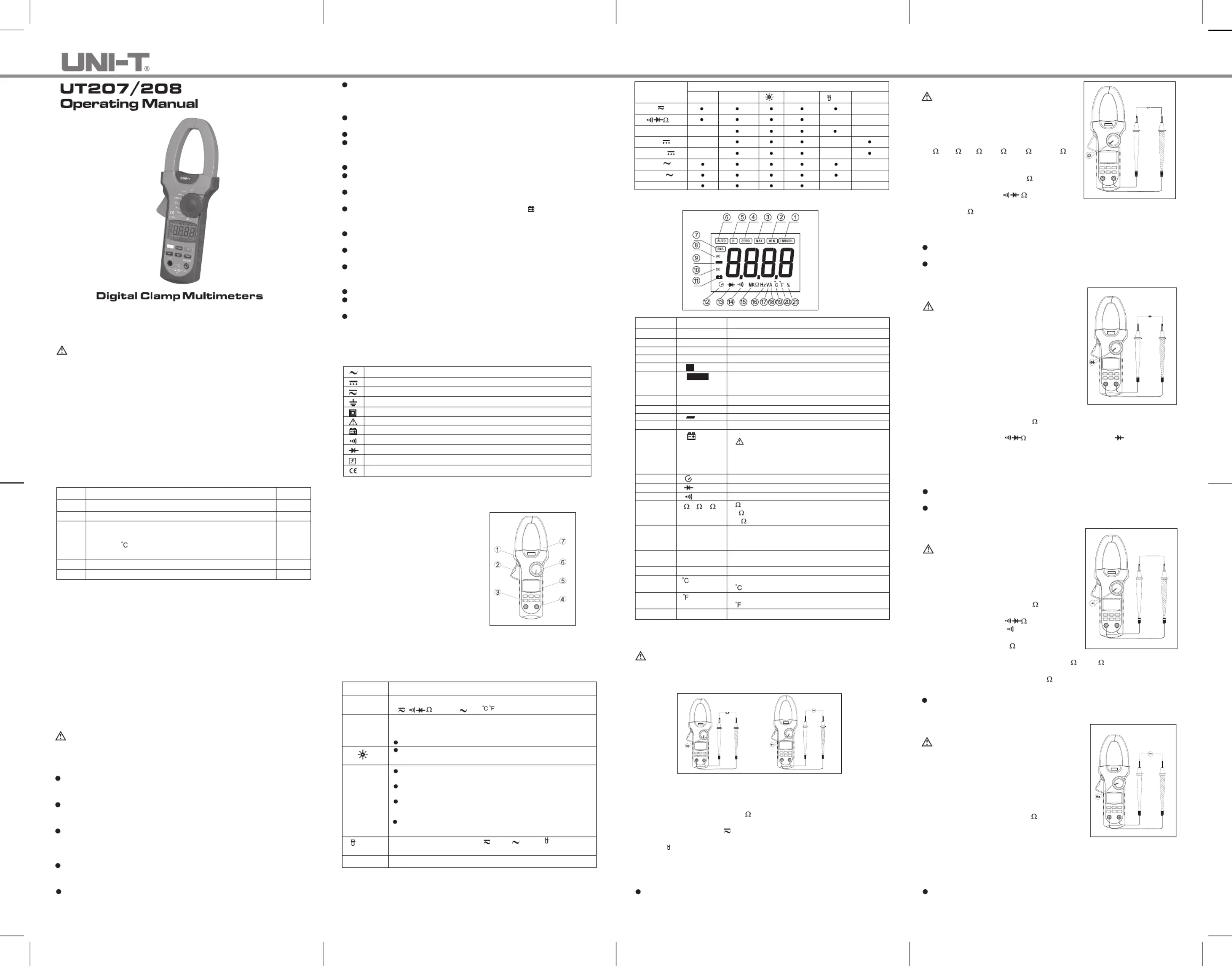
Figure 1
The Meter Structure (See Figure 1)
Handuahan Grd to prote user’s s:ctd
fromtoro uc t nhinghedageus area.
T erigger:pressthelevertoopenth
transformerjaws.Whenthepressur e
ontheleverisreleased,thejawswil l
close.
Functional Buttons
Input Terminals
LCD Display
Rotary Switch
T ransformerJadesgnedtow: i pi upck
t heACand DCcurren t f thlowinghroug
theconducto r. Itcouldtransfercurren t
tovoltage. Thetestedconductor must
verticallygothroughtheJawcente r.
1.
2.
3.
4.
5.
6.
7.
Press button to select the alternate functions includingSELECT
V
,
,,%HzA
and
(UT208 only).
Starts recording of maximum and minimum values.
Press to st t t ephedisplayhroughhigh(MAX) andlow (MN)readingI s
at any mode.
Press and hold for one second to exit MAX/MIN mode.
Press to turn on the backlight, repress to turn it off, otherwise
l automatically off after 1 minute.itwil
Functional Buttons
Below table indicated for information about the functional button operations.
Button Operation Performed
SELECT
MAX/MIN
Press to enter the Hold mode in any mode, the MeterHOLD
beeps.
PressHOLDagainto exit the Hold mode toreturn tomeasuremen t
mode, the Meter beeps.
Turning the rotary switch or pressing button can also SELECT
exit Hold mode.
HOLD
PresbuttonsHOLD forsecondswhen 2 turningontheMeter to
display full icon.
Whenthe Meterisat %Hz, V and A
, press Hztomeasur e
frequency and duty cycle.
Hz
ZEROZEROPress to zeroing the display before measuring DC current.
The Effectiveness of Functional Buttons
N i sw ilowoteveryfunctonalbuttonscanbeusedoneveryrotaryitchpositons. Be
t abledescribeon which rotary switch position the functions of buttons are available.
SELECTMAX/MIN
HOLD
Hz
ZERO
N/A
%Hz
66A
1000A
66A
1000A
N/A
N/A
N/A
N/A
N/AN/A
N/A
N/A
N/A
N/A
N/A
N/A
Rotary Switch
Positions
V
FunctionalButtons
o
C
o
F
Figure 2
Display Symbols (See Figure 2)
Number Symbol Meaning
1
2
3
4
5
6
7
8
9
10
11
INRUSH
MIN
MAX
ZERO
Indicator for Surge current
Minimum reading displayed
Maximum reading displayed
Indicator for zeroing
Data hold is active
TheMeterisintheautorangemodeinwhichth e
Meert auomaicallytt sts telecherange with t hebest
resolution.
True RMS indicator
Indicator for AC voltage or current
Indicates negative reading
Indicator for DC voltage or current
The battery is low.
W: To l s, charningavoidfasereadingwhi
couldleadtopossibleelectricshock or
personalinjur y, replacethebatteryassoon as
the battery indicator appears.
H
AUTO
RMS
AC
DC
12
13
14
15
16
17
18
19
20
21
Sleep mode is on
Test of diode
The continuity buzzer is on
: Ohm. The unit of resistance.
k
:Kilohm. 1x10
3
or 1000 ohms
M
:Megohm. 1x10
6
or 1,000,000 ohms
Hz: Hertz. The unit of frequency.
KHz: Kilohertz. 1x10
3
or 1000 hertz.
MHz: Meghertz. 1x10
6
or1,000,000 hertz.
Volts. The unit of voltage.
mV: Millivolt. 1x10
-3
or 0.001 volts
Amperes (amps). The unit of current.
The unit of temperature:
:Centigrade temperature
The unit of temperature:
:Fahrenheit temperature
Duty cycle measurement
,K,M
H MHzz,kHz,
mV, V
A
%
A. Measuring DC/AC ( See Figure 3 )
To avoid harm to you or damage to the Meter from eletric shock, do not
attempt to measure voltages higher than 600V AC/DC, although readings may
be obtained.
Red
Black
Red
Black
Measurement Operation
Figure 3
Warning
The DC Voltage ranges are: 6.6V, 66V and 600V
The AC Voltage ranges are: 6.6V, 66V and 600V
To measure DC/AC voltages, connect the Meter as follows:
Insert the red test lead into the V
Hz COM terminal and black test lead into the
terminal.
Set the rotary switch to V
.DC measurement mode and auto ranging is a
default. Press to switch to AC measurement mode.SELECT
Press
Hz u q l but buttontomeasrefreuencyordutycyce,thefrequecyut n or dy
cycle readings obtained from this range is only for reference.
Connect the test leads across with the object being measured.
The measured value shows on the display.
1.
2.
3.
4.
Note
When DC/AC voltage measurementhas beencompleted, disconnectthe connection
betweenthetestingleadsandthecircuitundertestandremovetestinglead s
from the input terminals.
B. Measuring Resistance (See Figure 4)
To avoid damage to theMeter orto thedevice s
under test, disconnect circuit power and
discarhge a llthe high-oltvage caacrspito berefo
measuring resistance.
The resistance ranges are:
660
, 6.6k, 66k, 660k, 6.6M and 66M
To measure resistance, connect the Meter as
follows:
Insertthe redtest leadintothe V
Hzterminal
and black test lead into the terminal. COM
Set trotary stcto he wih
. Resistcean
measurement is a default or press SELECT
to switch to
measurement mode.
1.
2.
Red
Black
Figure 4
Warning
Connect the test leads across with the object being measured.
The measured value shows on the display.
3.
Note
To tobain a more precise r, y c removet eadingououldheobjectsbeinged test from
the circuit during measurement.
When resistance measurement has been completed, disconnect the connection
between the testing leads and the circuit under test and remove testing leads
from the input terminals.
C. Testing Diodes (See Figure 5)
To avoiddamagetotheMeterorto thedevice s
undertest,disconnectcircuitpoweran d
dillscarhge a thhigh-olte vage caacrspito berefo
testing diodes.
Usethediodetestto checkdiodes,transistors,an d
othersemiconductordevices.Thediode testsend s
a ncurrentthroughthesemicondutorjunction,the
measurethevoltagedropacrossthejunction. A
goodsiliconjunctiondropsbetween0.5V and0.8 V.
To test the diode out of a circuit, connect the Meter
as follows:
Figure 5
Warning
Red
Black
Insert the red test lead into the terminal and black test lead into theVHz COM
terminal.
Set the rotary switch to
. Press to switch to measurementSELECT
mode.
For forward voltage drop readings on any semiconductor component, place the
red test lead on the component’s anode and place the black test lead on the
component’s cathode.
1.
2.
3.
Note
To tobain a more precise r, y c remove t eadingououldheobjebeingcts testfred om
the circuit during measurement.
Whendiodetestinghasbeen completed,disconnecttheconnectionbetweenth e
testing leads and the circuit under test and remove testing leads from the input
terminals.
D. Testing for Continuity (See Figure 6)
To avoiddamagtotheMeterorto thedevice s
undertest,disconnectcircuitpoweran d
dillscarhge a thhigh-olte vage caacrspito berefo
measuring continuity.
To test for continuity, connect the Meter as follows:
Insert the red test lead into the V
Hz terminal
and the black test lead into the terminal.COM
Set the rotary switch to
and press
SELECTbuttonto select
measurementmode.
The buzzer sounds if the resistance of a circuit
under test is less than 30
.
The buzzer may or may not sound if the
resstancie of a ciit er rcuundtest is bweteen 30 to 100 .
The buzzer does not sound if the resistance of
1.
2.
3.
RedBlack
Warning
Figure 6
a circuit under test is higher than 100
.
Note
Whencontinuitytestinghas beencompleted,disconnecttheconnection between
t ttg t t tt tt f theheesinleadsandhecircuiunderesandremoveesingleadsrom
input terminals.
E. Measuring Frequency (See Figure 7)
To avoid harm to you or damage to the Meter
fromeletricshock,donotattempttomeasur e
voltageshigherthan600VAC/DC,althoug h
readings may be obtained.
The frequency ranges are:
660Hz, 6., 6kHz66kHz, 660kHz, 6.6MHz and 66MHz.
To measurefrequenc y, connecttheMeteras follows:
Insert the red test lead into the V
Hz terminal
and the black test lead into the terminal.COM
Set the rotary switch to . Frequency%Hz
msuremt m is a feaenodedeault or pre ssSELECT
to switch to measurement mode.Hz
Connect the test leads across with the object being measured.
1.
2.
3.
Red
Black
Figure 7
Warning
Note
When frequency measurement has been completed, disconnect the connection
bet the i lea and weentestngdsthrce ciuit uer te and re the i sndst,movetestnglead
away from the input terminals of the Meter.
The measured value shows on the display.
Produktspezifikationen
| Marke: | Uni-T |
| Kategorie: | Messgeräte |
| Modell: | UT208 |
Brauchst du Hilfe?
Wenn Sie Hilfe mit Uni-T UT208 benötigen, stellen Sie unten eine Frage und andere Benutzer werden Ihnen antworten
Bedienungsanleitung Messgeräte Uni-T

1 September 2024
1 September 2024
1 September 2024
1 September 2024
1 September 2024
1 September 2024
1 September 2024
1 September 2024
1 September 2024
1 September 2024
Bedienungsanleitung Messgeräte
Neueste Bedienungsanleitung für -Kategorien-
16 Oktober 2024
16 Oktober 2024
16 Oktober 2024
16 Oktober 2024
16 Oktober 2024
16 Oktober 2024
16 Oktober 2024
16 Oktober 2024
16 Oktober 2024
16 Oktober 2024