Vitek VTC-TNB2FM Bedienungsanleitung
Vitek Sicherheitskamera VTC-TNB2FM
Lies die bedienungsanleitung für Vitek VTC-TNB2FM (128 Seiten) kostenlos online; sie gehört zur Kategorie Sicherheitskamera. Dieses Handbuch wurde von 7 Personen als hilfreich bewertet und erhielt im Schnitt 4.8 Sterne aus 7 Bewertungen. Hast du eine Frage zu Vitek VTC-TNB2FM oder möchtest du andere Nutzer dieses Produkts befragen? Stelle eine Frage
Seite 1/128
VITEK
VTC-TNB2FM
Transcendent Series
2 Megapixel H.265 Specialized
Facial Recognition Camera
with 2 White Light LEDs
QUICK START GUIDE
FOR FULL PRODUCT MANUAL
FOLLOW THE QR CODE BELOW
FEATURES
• 1/2.8” 2.0 Megapixel Progressive Scan CMOS image sensor
• Up to 30fps live view @ 2 MegaPixel (1920×1080)
• 7 ~ 22 mm, with recommended face capture b/w 15-50 feet
• 2 White Light LEDs with 65’ Range
• 120dB Super Wide Dynamic Range (WDR)
• True Mechanical Day/Night function by ICR
• XD-DNR (2D-DNR & 3D-DNR) Noise Reduction
• Pupil distance of facial images over 20 pixels can be detected
• Face snapshots enabled by precision detection, tracing, caputre, scoring
• Supports panorama capture and self-defined info overlay (device, ID, time, etc.)
• H.265/H.264/MJPEG Triple Streaming
• Secondary Video Output (CVBS)
• Remote Viewing via CMS, Internet Explorer, and iOS & Android Apps
• ONVIF Compliant
• IP67 Weather Resistance
• Optional Junction Box Mount Available (VT-TJB03)
• 12VDC & PoE (Power over Ethernet) Operation
1
2
3
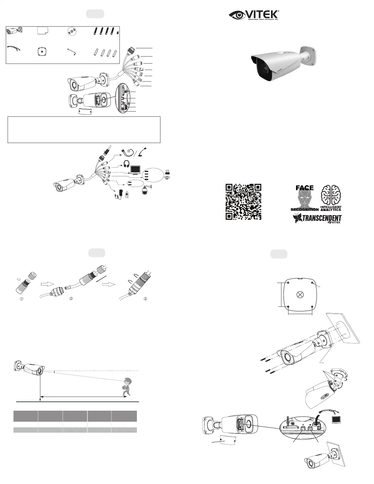
Components and Accessories
Overview
Alarm Connection
Weather Resistant Network Coupler
1. Loosen the nut from the Weather Resistant Network Coupler,
2. Run ethernet cable through coupler, then attach a RJ-45 connector.
3. Tighten the nut and coupler for a weather resistant seal.
Installation
Before beginning installation, make sure that the wall or ceiling is
strong enough to withstand 3 times the weight of the camera. The
mounting steps are as follows:
1. Attach the drill template to
the place where you want to
install the camera, then drill
screw holes and 1 cable
hole (if you want to route the
cables through the mounting
base) according to the drill
template
2. Route the cables and connect the power & video cables, use the
rubber plug to fill the gap of the mounting base
3. Secure the mounting base to the ceiling or
wall with screws.
Camera
Quick
start guide
CD
Plastic
plug × 4
DrilltemplateScrewdriver
4 tapping screws
1 machine screw
CVBS&DC
IN cables
1 Ethernet Connector *
2 MICAudio Input
3 HP AudioOutput
4 CVBSVideo Output
5 Alarm Input/Output
6 RS485
7 PowerConnector *
8Micro SD Card Slot
9 Zoom +
10 Zoom -
11 DC IN & CVBS Interface
12 Reset
ALM-COM
ALM-OPEN
ALM-INA
ALM-GND
RS485T+
RS485T-
DC12V/AC24V
Alarm Input: Join the grounding ends of the sensor and the camera and then connect the
signal cable of the sensor to the alarm input port of the camera.
Alarm Output: Loosen the screws in the alarm output port. Then insert the signal wires
of the alarm output devices into the port of COM and OPEN separately. Finally tighten
the screws. Some of the external alarm output devices need the power supply.
Securityc
a
p
1
3
4
5
6
7
2
8
9
10
11
12
* 1. It is recommended to install the
security cap for outdoor installation.
* 2. If the PoE switch is used to
power the camera, the DC12V/AC24
power supply is not required.
H
D
Surveillance
Width
Focal-length
Optimal Object
Distance
Installation
Height
Camera’s
Depression Angle
2.4m
6.0m
2.6m
2.4m
7-22mm (W)
7-22mm (T)
3.6m2.1m
10°
10°
Requirements of Camera Installation and Surrounding Areas
1.
The camera should be installed in front of the passage to take snapshots of full frontal faces.
2. Installation height ranges from 6.5 to 11.5 feet (2m - 3.5m), adjustable accodring to the
focal-length of different lenses and object differences.
3. The depression angle (*) of the camera shall be less than or equal to 15°
4. The object distance (D) depends on the focal-length of the lens mounted in the camera.
5. To ensure accuracy, captured faces can only deviate <30° left / right or 20° up / down.
6. Make sure the detected face is clear and has adequate, even light. Otherwise, enable white
light mode to compensate (especially when there is too much darkness on the detected face).
7. The following crowded scenes are not applicable: airports, railway stations, town squares,
intersections). Backlit scenes are also unapplicable.
Installing the Camera
64.6mm
64.6mm
∅5
Mounting Base
Adjust the bracket. Before adjustment, preview
the camera image on a monitor
(see step 5). Loosen the fixed
screws to adjust the view
angle of the camera. After,
tighten the fixed screws.
4.
Insert a micro
SD card
Zoom+
Zoom-
Monitor
Cover
Open the cover of the camera as shown in the
figure below, then insert a micro SD card. Then
press the T/W button to obtain an optimum
image. View on a monitor and adjust as
necessary.
5.
6. Install the cover evenly back on the camera and fix it firmly
with screws.
FixedScrews
Pan360°
Tilt90°
Rotate
360°
*
•
Micro SD Card support up to 128GB
Produktspezifikationen
| Marke: | Vitek |
| Kategorie: | Sicherheitskamera |
| Modell: | VTC-TNB2FM |
Brauchst du Hilfe?
Wenn Sie Hilfe mit Vitek VTC-TNB2FM benötigen, stellen Sie unten eine Frage und andere Benutzer werden Ihnen antworten
Bedienungsanleitung Sicherheitskamera Vitek

29 März 2026
28 März 2026
26 März 2026
23 März 2026
22 März 2026
21 März 2026
20 März 2026
17 März 2026
15 März 2026
14 März 2026
Bedienungsanleitung Sicherheitskamera
Neueste Bedienungsanleitung für -Kategorien-
31 März 2026
31 März 2026
31 März 2026
31 März 2026
31 März 2026
29 März 2026
29 März 2026
29 März 2026
29 März 2026
27 März 2026