Yard Force YF-RER38-BG Bedienungsanleitung
Yard Force Rasenmäher YF-RER38-BG
Lies die bedienungsanleitung für Yard Force YF-RER38-BG (4 Seiten) kostenlos online; sie gehört zur Kategorie Rasenmäher. Dieses Handbuch wurde von 44 Personen als hilfreich bewertet und erhielt im Schnitt 4.7 Sterne aus 3 Bewertungen. Hast du eine Frage zu Yard Force YF-RER38-BG oder möchtest du andere Nutzer dieses Produkts befragen? Stelle eine Frage
Seite 1/4
YF-RER38-BG BAGGING KIT
FOR USE WITH YARD FORCE RIDING LAWN MOWER
WARNING:
To reduce the risk of injury, user must read and understand the operator’s manual for their riding
lawn mower before using this accessory. Save these instructions. Refer to them frequently and use
them to instruct other users. If you loan someone this product, loan them these instructions also.
PACKING LIST
Bagging Blades (2) Bagger Bracket
Hitch Pin Bagger Cover
Bags (2) Upper Bagger Tube
Lower Bagger Tube
INSTALLING THE BAGGING KIT
This kit includes a bagger and special mower blades
designed to be used when bagging. Install the blades rst,
then install the bagging kit.
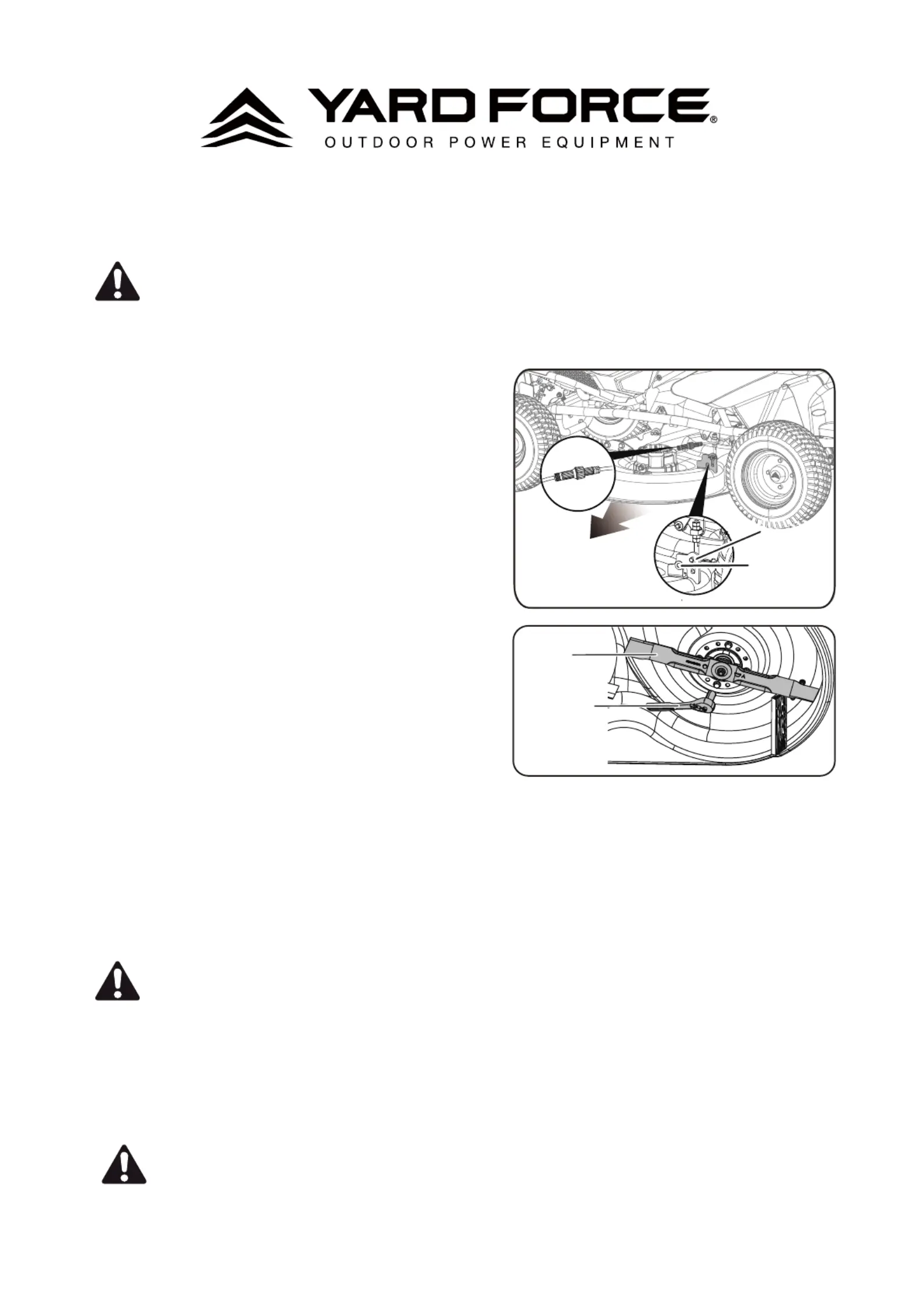
REMOVING THE CUTTING DECK
See Figure 1.
If desired, the cutting deck can be removed from the mower
to make accessing the blades easier when changing.
• Make sure direction control switch is in neutral (N)
position and blade engage knob is down.
• Stop the motor, wait for the blades to come to a
complete stop, remove the start key, and set the
parking brake.
• Place a large piece of cardboard or similar beneath the
deck to prevent scratching.Disconnect the (2) cables
that connect the cutting deck to the mower.
• Lower the cutting deck to its lowest position.
• Remove the 4 hitch pins and washers that secure the
cutting deck in place.
• Slide the deck out from under the mower.
• Reverse the process to reattach the cutting deck to the mower.
INSTALLING BAGGING BLADES
See Figures 2 - 3.
CAUTION:
Only use replacement blade hardware authorized by the manufacturer of your riding mower. Use
of blade bolts not authorized is hazardous and may damage your riding mower.
• Make sure direction control switch is in neutral (N) position and blade engage knob is down.
• Stop the motor, wait for the blades to come to a complete stop, remove the start key, and set the
parking brake.
• Raise the height of the cutting deck to its highest position to allow access to blades.
NOTE: If necessary, raise the mower by placing on a lift or using a jack and jack stands, or remove the
cutting deck as described in the previous section to gain access.
WARNING:
If raising the mower to access the blades, make sure the mower is properly secured and the
parking brake is set before proceeding. Failure to properly secure the mower could cause it to fall,
resulting in possible death or serious personal injury.
CUTTING DECK
HITCH PIN
WASHER
Fig. 1
Fig. 2
Wrench
Blade
CABLE
Produktspezifikationen
| Marke: | Yard Force |
| Kategorie: | Rasenmäher |
| Modell: | YF-RER38-BG |
Brauchst du Hilfe?
Wenn Sie Hilfe mit Yard Force YF-RER38-BG benötigen, stellen Sie unten eine Frage und andere Benutzer werden Ihnen antworten
Bedienungsanleitung Rasenmäher Yard Force

30 August 2025
29 August 2025
29 August 2025
29 August 2025
29 August 2025
29 August 2025
29 August 2025
29 August 2025
12 August 2025
25 Juli 2025
Bedienungsanleitung Rasenmäher
Neueste Bedienungsanleitung für -Kategorien-
30 März 2026
30 März 2026
30 März 2026
29 März 2026
27 März 2026
27 März 2026
27 März 2026
27 März 2026
26 März 2026
26 März 2026