APC AP7768 Bedienungsanleitung
APC
Nicht kategorisiert
AP7768
Lies die bedienungsanleitung für APC AP7768 (2 Seiten) kostenlos online; sie gehört zur Kategorie Nicht kategorisiert. Dieses Handbuch wurde von 58 Personen als hilfreich bewertet und erhielt im Schnitt 4.7 Sterne aus 29.5 Bewertungen. Hast du eine Frage zu APC AP7768 oder möchtest du andere Nutzer dieses Produkts befragen? Stelle eine Frage
Seite 1/2

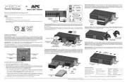
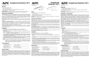
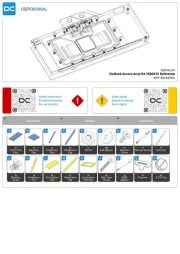
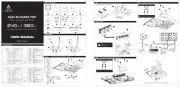
Rack Automatic Transfer Switch Front
and Rear Rail Kit(AP7768)—Installation
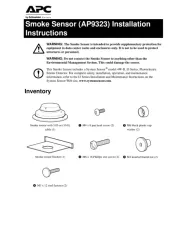
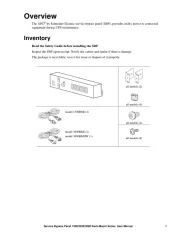
Inventory
Note: These instructions apply to both 1U and 2U Rack Automatic Transfer Switches.
Attach the mounting brackets
Attach the left and right mounting brackets to
the unit, using two Phillips flat-head screws
(provided) for each bracket. Place the brackets
flush with the front of the rack to leave room
for routing cables.
Disassemble the adjustable brackets
The adjustable brackets are necessary only if you are using a four-post enclosure or rack. If you are using a
two-post rack, the Automatic Transfer Switch is supported by the mounting brackets alone.
1. Disassemble each adjustable bracket by removing
the slide screw and nut.
2. Set the screws, nuts, and adjustable bracket
segments aside.
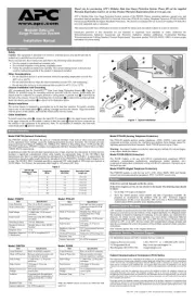
Front and rear rail segments (2 each)
Hex nuts (2) Washers (4) Phillips pan-head
screws (2)
Phillips flat-head
screws (4)
Phillips flat-head
mounting screws (4)
pdu0400a
pdu0403a

Customer support and warranty information is available at the APC Web site, www.apc.com.
© 2007 American Power Conversion. All rights reserved. All APC trademarks are property of American Power
Conversion. Other trademarks are property of their respective owners.
990-3169
06/2007
*990-3169*
Attach rear segments to the rack
1. Insert cage nuts (provided with
your enclosure) on the rear
vertical mounting rails of the
enclosure at your chosen
location.
2. Align the rear segments of the
adjustable bracket with the cage
nuts you inserted in step 1.
3. Insert and tighten the Phillips
flat-head mounting screws
(provided).
Attach front segments to the switch
1. Align the front segments of the
adjustable bracket with the four
corresponding holes on the
sides of the Automatic Transfer
Switch (ATS).
2. Attach both front segments to
the ATS using two Phillips
pan-head screws (provided) for
each bracket segment.
Install the Automatic Transfer Switch in the enclosure
Heavy: Two people should perform this procedure.
1. Position the Automatic
Transfer Switch in front of
the mounted rear adjustable
bracket segments.
2. Align the front and rear
adjustable bracket segments,
and slide the front segments
onto the rear segments.
3. Align the mounting brackets
on the switch with the front
vertical mounting rails of the
enclosure and insert cage
nuts (provided with your enclosure) in the appropriate holes on the front vertical mounting rails.
4. Insert and tighten the Phillips flat-head mounting screws (provided).
5. Insert slide screws and nuts (see “Disassemble the adjustable brackets”) into each adjustable
bracket, and tighten them to secure the positions of the adjustable brackets.
pdu0402a
pdu0404a
Produktspezifikationen
| Marke: | APC |
| Kategorie: | Nicht kategorisiert |
| Modell: | AP7768 |
Brauchst du Hilfe?
Wenn Sie Hilfe mit APC AP7768 benötigen, stellen Sie unten eine Frage und andere Benutzer werden Ihnen antworten
Bedienungsanleitung Nicht kategorisiert APC
25 Juli 2025
15 Juli 2025
11 Juli 2025
11 Juli 2025
11 Juli 2025

11 Juli 2025
11 Juli 2025
11 Juli 2025
11 Juli 2025
11 Juli 2025
Bedienungsanleitung Nicht kategorisiert
- Napoleon
- Christopeit
- DMAX
- Mercusys
- Dirt Devil
- Kingston Technology
- Serge
- Hobart
- BBB
- Positive Grid
- Sikkens
- Really Right Stuff
- Prism Sound
- Beeitzie
- Ave Six
Neueste Bedienungsanleitung für -Kategorien-

29 Juli 2025

29 Juli 2025

29 Juli 2025
29 Juli 2025

29 Juli 2025

29 Juli 2025
29 Juli 2025
29 Juli 2025

29 Juli 2025