Califone PA-IRSYS Bedienungsanleitung


Lies die bedienungsanleitung für Califone PA-IRSYS (6 Seiten) kostenlos online; sie gehört zur Kategorie Lautsprecheranlage. Dieses Handbuch wurde von 2 Personen als hilfreich bewertet und erhielt im Schnitt 4.3 Sterne aus 1.5 Bewertungen. Hast du eine Frage zu Califone PA-IRSYS oder möchtest du andere Nutzer dieses Produkts befragen? Stelle eine Frage

Seite 1/6
Califone® International Inc. • 1145 Arroyo Avenue, # A • San Fernando, CA 91340 USA
Toll Free 800.722.0500 | Toll Free Fax 877.402.2248
International Customers call 818.407.2400 or Fax 818.407.2405 califone.com
October 2008
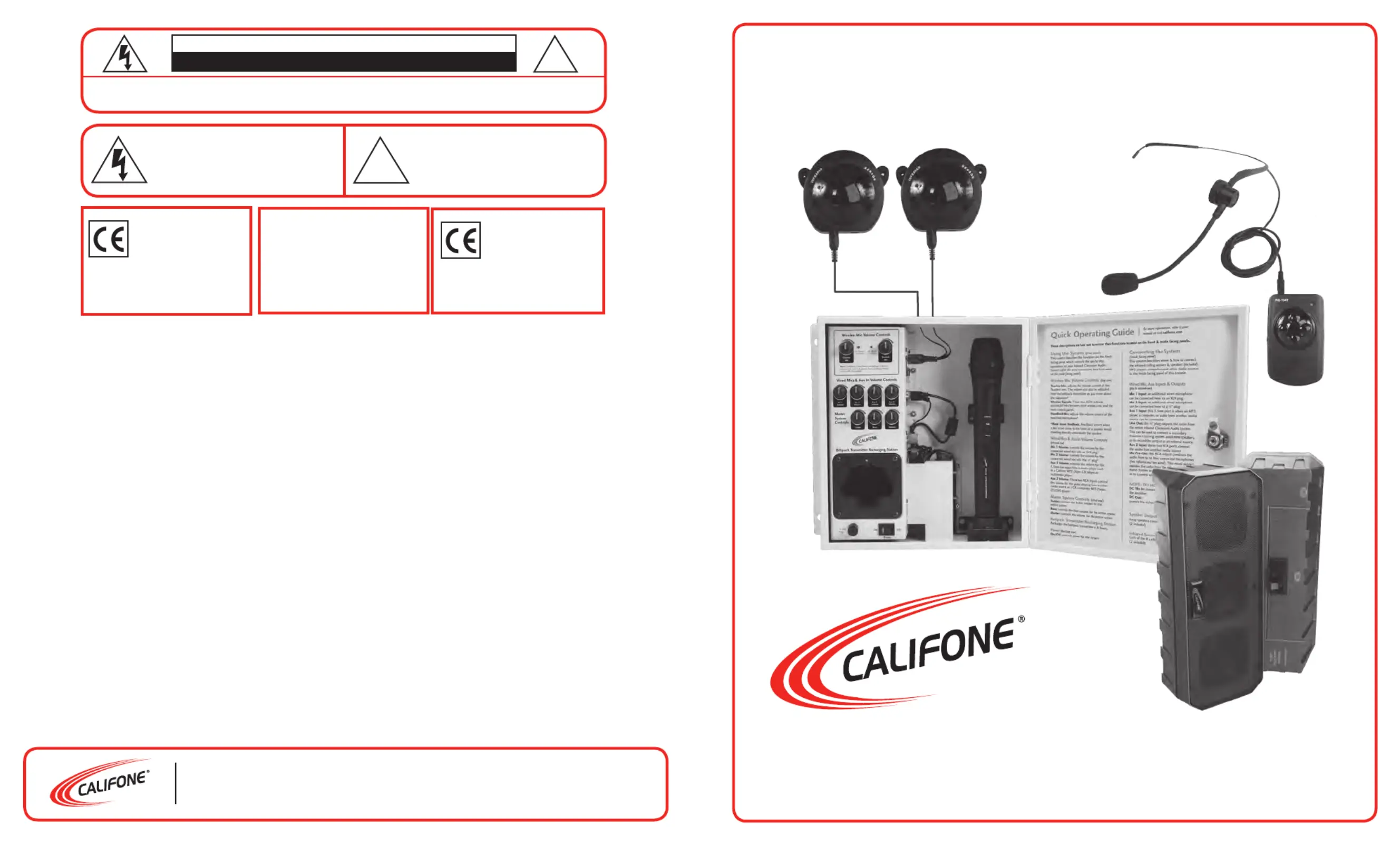
PA-IRSYS Operating Instructions
Infrared Classroom Audio System
ATTENTION: ALL SAFETY AND OPERATING INSTRUCTIONS
SHOULD BE READ BEFORE OPERATING APPLIANCE. ALL
ED WHEN OPERATING THE APPLIANCE. HEED AND ADHERE
TO ALL WARNINGS ON THE APPLIANCE AND IN THE OPERATING
INSTRUCTIONS. RETAIN ALL SAFETY AND OPERATING
INSTRUCTIONS FOR FUTURE REFERENCE.
WATER & MOISTURE - DO NOT USE THE APPLIANCE NEAR
WATER; IE. BATHTUB, WASHBOWL, KITCHEN SINK, LAUNDRY
TUB, WET BASEMENT OR SWIMMING POOL.
VENTILATION - DO NOT SITUATE THE APPLIANCE SO THAT
ITS LOCATION OR POSITION INTERFERES WITH ITS PROPER
VENTILATION. FOR EXAMPLE, THE APPLIANCE SHOULD NOT
BE SITUATED ON A BED, SOFA, RUG OR SIMILAR SURFACE THAT
MAY BLOCK THE VENTILATION OPENINGS. THE
APPLIANCE SHOULD NOT BE PLACED IN A BUILT-IN
INSTALLATION, SUCH AS A BOOKCASE OR CABINET, THAT
MAY IMPEDE THE FLOW OF AIR THROUGH THE VENTILATION
OPENINGS.
HEAT - SITUATE THE APPLIANCE AWAY FROM HEAT SOURCES
SUCH AS RADIATORS, HEAT REGISTERS, STOVES OR OTHER
APPLIANCES (INCLUDING AMPLIFIERS) THAT PRODUCE HEAT.
POWER SOURCES - CONNECT THE APPLIANCE ONLY TO
A POWER SUPPLY TYPE DESCRIBED IN THE OPERATING
INSTR-UCTIONS OR MARKED ON THE APPLIANCE.
GROUNDING OR POLARIZATION - PRECAUTIONS SHOULD
BE TAKEN SO THAT THE GROUNDING OR POLARIZATION
MEANS OF THE APPLIANCE ARE NOT DEFEATED.
POWER CORD PROTECTION - POWER SUPPLY CORDS
SHOULD BE ROUTED SO THAT THEY ARE NOT LIKELY TO
BE WALKED ON OR PINCHED BY ITEMS PLACED UPON OR
AGAINST THEM, PAYING PARTICULAR ATTENTION TO CORDS
AT PLUGS, CONVENIENCE RECEPTACLES, AND THE POINT
WHERE THEY EXIT FROM THE APPLIANCE.
CLEANING - THE APPLIANCE SHOULD BE CLEANED ONLY
AS RECOMMENDED BY THE MANUFACTURER.
NON USE PERIODS - UNPLUG THE APPLIANCE POWER
CORD FROM THE OUTLET WHEN LEFT UNUSED FOR A
LONG PERIOD OF TIME.
OBJECT & LIQUID ENTRY - CARE SHOULD BE TAKEN SO
THAT OBJECTS DO NOT FALL AND LIQUIDS ARE NOT SPILLED
INTO THE ENCLOSURE THROUGH OPENINGS.
DAMAGE REQUIRING SERVICE - THE APPLIANCE SHOULD
BE SERVICED BY QUALIFIED SERVICE PERSONNEL WHEN:
(A) THE POWER SUPPLY CORD OR THE PLUG HAS BEEN
DAMAGED (B) OBJECTS HAVE FALLEN OR LIQUID HAS BEEN
SPILLED INTO THE APPLIANCE (C) THE APPLIANCE HAS BEEN
EXPOSED TO RAIN (D) THE APPLIANCE DOES NOT APPEAR TO
BE OPERATING NORMALLY OR EXHIBITS A MARKED CHANGE
IN PERFORMANCE (E) THE APPLIANCE HAS BEEN DROPPED
OR THE ENCLOSURE DAMAGED.
SERVICING - THE USER SHOULD NOT ATTEMPT TO SERVICE
THE APPLIANCE BEYOND THAT DESCRIBED IN THE OPERATING
INSTRUCTIONS. ALL OTHER SERVICING REFER TO A QUALIFIED
SERVICE PERSONNEL.
IMPORTANT SAFETY INSTRUCTIONS
CAUTION: TO REDUCE THE RISK OF ELECTRIC SHOCK, DO NOT REMOVE COVER OR BACK.
NO USER SERVICEABLE PARTS INSIDE. REFER SERVICING TO QAULIFIED PERSONNEL.
CAUTION
RISK OF ELECTRIC SHOCK - DO NOT OPEN
This product is not designed to
function normally in strong electro-
magnetic elds. Consequently, the
audio quality may degrade while the
product is exposed to strong electromagnetic elds.
Normal audio quality operation will be recovered
when the strong electromagnetic eld is no
longer present.
Ce produit n’est pas conçu pour
un fonctionnement dans de forts
champs électromagnétiques. Par
conséquent, la qualité sonore peut
diminuer si ce produit est exposé à
un fort champ életromagnétique. La qualité sonore
redeviendra normale après affaib-lissement du
champ électromagnétique.
The lightening ash with arrowhead
within a triangle is intended to tell the
user that parts inside the product are a
risk of electric shock to persons.
The exclamation point within a
triangle is intended to tell the user
that important operating and servicing
instructions are in the papers with
the appliance.
WARNING:
TO REDUCE THE RISK OF
FIRE OR ELECTRIC SHOCK, SO
NOT EXPOSE THIS APPLIANCE
TO RAIN OR MOISTURE.
!
!
1 2
Thank you for purchasing the Califone
®
PA-IRSYS Infrared Classroom Audio System.
We encourage you to visit our website www.califone.com to register your product for its warranty coverage, to sign up to receive
our newsletter, download our catalog, and learn more about the complete line of Califone
®
audio visual products, including
portable and installed wireless PA systems, multimedia players and recorders, headphones and headsets, computer peripheral
equipment, visual presentation
products and language learning materials.
Unpacking the Unit
Inspect the unit once the packaging has been opened for any
damage occurred during shipping & contact us immediately.
Please keep the packing material for further use.
Warranty Registration
Califone warrants the Infrared Classroom Audio System to
be free from defective material and workmanship for one
year from the purchase date (six years for the speakers).
Our “Project Intercept” Customer Satisfaction program will
replace defective parts and repair malfunctioning equipment
under this warranty when the defect occurs under normal use.
All Damage Claims Must Be Made With The Freight Carrier
Notify the freight carrier immediately if you observe any
damage to the shipping carton or product. Repack the unit
in the carton and await inspection by the carrier’s claim
agent. Notify your dealer of the pending freight claim.
Returning Your Unit for Service or Repairs
Should your unit require service, contact our Customer
Service Department online at califone.com/techsupport
or via email warranty@califone.com 800- or by phone at
722-0500 / 818-407-2400 to rst obtain an RA number
before returning it back to Califone. The unit must be returned
to our factory via prepaid transportation only after the
factory issues an RA (Return Authorization) number
which must be clearly written on the outside of the box.
Two infrared ceiling sensors (PI30-SENSOR),
each with an integrated 32’ connecting cable
• HBM-316 microphone used with beltpack transmitter
Teacher Beltpack transmitter (PI30-BP)
• Beltpack lanyard with neck strap
• Student handheld microphone (PI30-HH)
• Four 1.2V AA Rechargeable NiMH batteries (for use
with handheld and beltpack microphones)
Two non-powered PI30-SP
PA-IRSYSB
• PA-IRSYS with two additional powered
(PI30-PS) array speakers
Control Panel Descriptions
Vi si t u s o n li n e at c a li fo n e. co m
PA-IRSYS Infrared Classroom Audio System
Operating Instructions
Front View Forward Facing Panel
(1) Power Switch
(2) Main Power Fuse (3.15A)
(3) IR Teacher Mic Volume Control
(4) IR Student Mic Volume Control
(5) IR Signal Indicator (Teacher Mic)
(6) IR Signal Indicator (Student Mic)
(7) Mic 1 Volume Control
(8) Mic 2 Volume Control
(9) Aux 1 Volume Control
(10) Aux 2 Volume Control
(11) Treble Level Control
(12) Bass Level Control
(13) Master Volume Control
(14) Beltpack Transmitter Recharging Station
(15) Beltpack Transmitter Recharge Status Indicator
(16) Power Adapter
(17) Handheld Microphone Recharging Station & Status Indicator
(18) Handheld Mic Holder
(19) Door Lock
Front View Inside Panel
(20) Mic 1 Input (Balanced XLR)
(21) Mic 2 Input (Unbalanced 1/4”)
(22) Aux Input 1 (3.5mm)
(23) Line Output (Mono 1/4”)
(24) Aux Input 2 (Stereo RCA)
(25) Mic Pre-out (Mono RCA)
(26) DC 18V In
(27) DC Out
(28) Speaker Output (+ terminal)
(29) Speaker Output (- terminal)
(30) Infrared Ceiling Sensor Input (B)
(31) Infrared Ceiling Sensor Input (A)
(32) Cable Holder
(33) Paging Input Volume Control
(34) Paging Input Jack
(35) 25V / 70V Paging Input Sensitivity Switch
Top and Bottom Views
(36) Panel Door
(37) AC Input
(38) Knockouts to feed wires through
(2)
(1)
(3)
(4)
(8)
(7)
(11)
(14)
(16) (17)
(19)(5) (6) (9) (10)(13) (12)(18)
(15)
Top View
Front View, Front Facing Panel
(For Sound Adjustments)
Front View, Inside Facing Panel
(For System Connections)
Bottom View
(20)
(26 )
(28)
(21)
(24)
(29)
(27)
(22 )
(23)
(25)
(30) (31)
(32)
(35)
(34)
(33)
(38)
(36)
(37)
(38)
3 4
Beltpack Transmitter and Mic Description
Vi s it u s on l i ne a t ca l i fo n e. c om
Infrared Ceiling Sensors (two units are included)
(1) Receiver Cover
(2) Fixed Ear
(3) Infrared External Input
(4) Infrared External Output
(5) Signal Cable with 32’ cord
2
1
2
1
3
4
5
Installation
Vi s it u s on l i ne a t ca l i fo n e. c om
Beltpack Transmitter Transmits Voice to the Infrared Ceiling Sensors
(1) Power LED Indicator
(2) Power Switch
(3) Battery Cover
(4) Infrared Transmitting Head
(5) MIC-IN Jack
(6) DC-IN Jack/Battery Charger
(7) Volume Control
(8) Belt Clip
(9) Battery Compartment
(5)
(4)
(1)
(2)
(3)
(6)
(7)
(8)
(9)
Speakers
CAUTION: The included PI30-SP speakers have a total impedance of
about 5.3 ohms when connected in parallel. Therefore, no more
than 2pcs PI30-SP should be connected to the PA-IRSYS to avoid
the impedance dropping too low for the amplier output. Speakers
with higher impedance ratings can be used as long as the total
load impedance on the amplier is not below approximately
3 ohms.
1. Install each of the PI30-SP non-powered speakers on
the front & back walls of the room. Optimal placement is
approximately 3 feet below the ceiling in the middle of
the wall.
Note: If the PA-IRSYSB package has been purchased, then 4
speakers (2 non-powered + 2 powered) can be connected to
the PA-IRSYS Control Panel. The PI30-SP (non-powered) speakers
should be connected as described above. The PI30-PS speakers
should be connected as follows:
1. Install the PI30-PS speakers on the wall in the desired locations.
2. Connect the line output (1/4”) of the control panel to one of
the line inputs on one of the PI30-PS speakers (RCA jacks).
3. Connecting the second PI30-PS speaker:
4. Option 1: The speakers can be daisy-chained by connecting
one of the line outputs (variable or xed) on one PI30-PS
speaker to the line input of the other PI30-PS speaker.
5. Option 2: A splitter may be put on the line output from
the control panel so that each PI30-PS speaker is fed with
its own cable.
6. Volume adjustment: Depending on if the speakers are
daisy chained and if the xed or variable line outputs,
were used, the method to adjust the volume will be
dierent. Adjust the volume levels of each of the speakers
to achieve a balanced sound eld in the listening area.
Infrared Ceiling Sensors
1. Install the two included infrared ceiling sensors along
an imaginary center line in the middle of the ceiling, with
each sensor located approximately one third of the length
of the room away from the back or front wall.
Note: With proper installation, the Classroom Audio system
(with two ceiling sensors) can be used in rooms up to 2,000 sq.
feet in size. If greater coverage is needed, up to 4 ceiling sensors
can be daisy-chained & connected to the control panel.
Tip: If reception of the infrared microphones is noisy or the
signal cuts out, try moving and/or rotating the receivers until
better reception is obtained.
Control Panel
The Control Panel has two possible mounting congurations:
1. Option 1: The default conguration is the surface-
mount the box on the wall. The mounting ears are
designed with 4 holes for screws. Wall anchors or other
hardware should be used as necessary to securely
attach the box to the wall.
2. Option 2: The second conguration is a ush-mount. The
mounting ears can be unscrewed, ipped around and
unscrewed into the holes towards the front of the box.
In this conguration, a hole will need to be made in
the wall the same size as the control panel. The control
panel will protrude from the wall only enough to allow
for the door to open fully.
Tips:
Install the panel in an accessible area of the classroom
where computers and other external media sources
can be easily connected to the panel.
Note that longer runs of cable and poorly shielded
cable can cause hum or other noise to enter the system
and output through the speakers and other outputs.
Plug the power of dierent equipment into the same
power outlet when possible to avoid ground loops. Also
see Connecting the System on the right side of the
inner door panel.
Connecting the System Once the
Control Panel is Installed
Note: The connections described in the following section
are found on the the inside facing panel of the control box.
1. Connect the two PI30-SP speakers to the Speaker
Output Jacks (28, 29).
2. Connect the two individual or daisy-chained signal
cables from the infrared ceiling sensors to the Infrared
Ceiling Sensor Jacks (30, 31).
3. Connect the AC power cord to the Power Connector
(34) on the bottom of the Control Panel and then to the
wall outlet.
4. If an external amplier or assistive listening system is
used, connect the amplier/assistive listening system
input to the (23).Line Output Jack
5. When using an external sound source (such as a DVD/
VCR, computer or a Califon media player), connect
the output from the media source to one of the Aux In
Jacks (22, 24). Depending on the cable you have and
the output jack type of the external source, you may
use either 3.5mm jack (Aux 1) or the RCA jacks (Aux 2). All
HBM-316 microphone
shown with PI30-BP
beltpack transmitter
PI30-HH
handheld student
microphone


Produktspezifikationen

Marke: Califone
Kategorie: Lautsprecheranlage
Modell: PA-IRSYS

Brauchst du Hilfe?

Wenn Sie Hilfe mit Califone PA-IRSYS benötigen, stellen Sie unten eine Frage und andere Benutzer werden Ihnen antworten