CyberPower CP2000PFCRM2U Bedienungsanleitung
CyberPower Unterbrechungsfreies Stromversorgungssystem CP2000PFCRM2U
Lies die bedienungsanleitung für CyberPower CP2000PFCRM2U (2 Seiten) kostenlos online; sie gehört zur Kategorie Unterbrechungsfreies Stromversorgungssystem. Dieses Handbuch wurde von 15 Personen als hilfreich bewertet und erhielt im Schnitt 5.0 Sterne aus 5 Bewertungen. Hast du eine Frage zu CyberPower CP2000PFCRM2U oder möchtest du andere Nutzer dieses Produkts befragen? Stelle eine Frage
Seite 1/2
7
CP1500PFCRM2U
7
CP2000PFCRM2U
PRODUCT REGISTRATION
YOUR ULTIMATE ALLY IN POWER
CP1500PFCRM2U/CP2000PFCRM2U
USER MANUAL
1 2 3
4
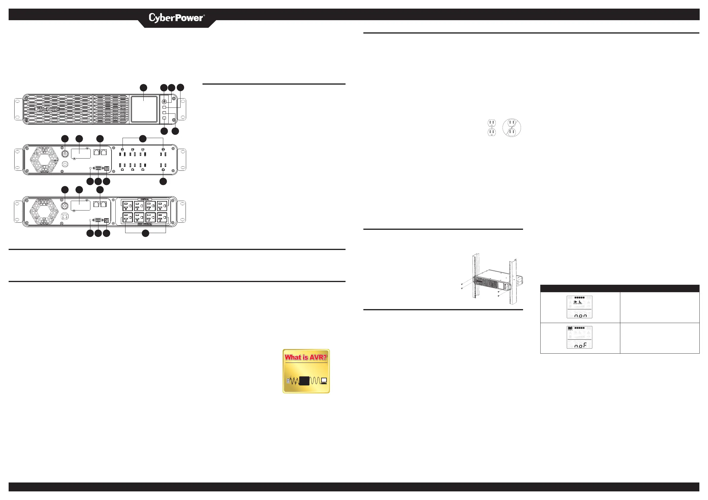
FEATURES
1 . LCD module display
2 . Power On Indicator
3 . Power Switch
6
5
4 . Up/Display button
8 9 10
5 . Down/Mute button
6 . Enter/Setup Button
7 . Circuit Breaker
8 . Expansion Slot
9 . Communication Protection Ports RJ45
11 12 13 14
10 . Battery and Surge Protected Outlets
8 9
*Critical /Non-critical (CP2000PFCRM2U only)
1 1 . Wiring Fault Indicator (Red)
12 . Contact signal
13 . USB Port to PC
14 . Widely Spaced Outlets Designed for AC Adapters
(For CP1500PFCRM2U only)
11 12 13 10
Thank you for purchasing a CyberPower product. Please take a few minutes to register your product at: cyberpowersystems.com/registration. Registration certifies your product's warranty,
confirms your ownership in the event of a product loss or theft and entitles you to free technical support. Register your product now to receive the benefits of CyberPower ownership.
IMPORTANT SAFETY WARNINGS (SAVE THESE INSTRUCTIONS)
When using electrical appliances, basic safety precautions should always be followed to
reduce the risk of fire, electric shock, and/or injury to persons including the following. This
Manual Contains Important Instructions that should be followed during installation and
the unit and unplug it from the AC power
source before servicing the battery.
CAUTION! Not for use in a computer
room as defined in the Standard for the
Protection of Electronic Computer/Data
Processing Equipment, ANSI/NFPA 75.
INSTALLING YOUR UPS SYSTEM - Continued
HARDWARE INSTALLATION GUIDE
1. Your new UPS may be used immediately upon receipt. However, after receiving a new
UPS, to ensure the battery’s maximum charge capacity, it is recommended that you
charge the battery for at least 8 hours. Your UPS is equipped with an auto-charge
feature. When the UPS is plugged into an AC outlet, the battery will automatically
charge whether the UPS is turned on or off.
Note: This UPS is designed with a safety feature to keep the system from being
turned on during shipment. The first time you turn the UPS on, you will need to have it
connected to AC power or it will not power up.
2. With the UPS unit turned off and unplugged, connect your computer, monitor, and any
other peripherals requiring battery backup into the battery power supplied outlets. DO
NOT plug a laser printer, paper shredder, copier, space heater, vacuum, sump pump
or other large electrical devices into the “Battery and Surge Protected Outlets”. The
power demands of these devices may overload and damage the UPS.
3. Plug the UPS into a 2 pole, 3 wire grounded receptacle (wall
outlet). Make sure the wall branch outlet is protected by a fuse
or circuit breaker and does not service equipment with large
electrical demands (e.g. air conditioner, copier, etc…). The
warranty prohibits the use of extension cords, outlet strips, and
surge strips.
4. Press the power switch to turn the unit on. The Power On indicator light will illuminate
and the unit will “beep”. If an overload is detected, an audible alarm will sound and
the unit will emit one long beep. To correct this, turn the UPS off and unplug at least
one piece of equipment from the battery power supplied outlets. Make sure the circuit
breaker is depressed and then turn the UPS on.
5. To maintain optimal battery charge, leave the UPS plugged into an AC outlet at all
times.
6. To store the UPS for an extended period, cover it and store with the battery fully
charged. While in storage, recharge the battery every three months to ensure battery
life.
7. Ensure the wall outlet and UPS are located near the equipment being attached for
proper accessibility.
RACK INSTALLATION (OPTION)
1. Remove all equipment connected to the product.
2. Make sure the product is turned off and
disconnected from AC power source.
3. Use the supplied truss head screws to secure the
UPS to your existing rack system.
REPLACING THE BATTERY
Replacement of batteries located in an OPERATOR ACCESS AREA.
1. When replacing batteries, replace with the same number of the following battery:
CyberPower/RB1290X2D for CP1500PFCRM2U, CyberPower/RB1290X2G for
CP2000PFCRM2U
2. CAUTION! Risk of Energy Hazard, 24 V, maximum 9.4 Ampere-hour battery. Before
replacing batteries, remove conductive jewelry such as chains, wrist watches, and
rings. High energy conducted through these materials could cause severe burns.
3. CAUTION! Do not dispose of batteries in a fire. The batteries may explode.
4. CAUTION! Do not open or mutilate batteries. Released material is harmful to the skin
and eyes. It may be toxic.
5. CAUTION: A battery can present a risk of electrical shock and high short circuit
current. The following precautions should be observed when working on batteries:
1) Remove watches rings, or other metal objects.
2) Use tools with insulated handles.
CAUTION - RISK OF EXPLOSION IF BATTERY IS REPLACED BY AN INCORRECT TYPE.
DISPOSE OF USED BATTERIES ACCORDING TO LOCAL REGULATIONS.
BASIC OPERATION
1. LCD module display
High resolution and intelligent LCD display shows all the UPS information using icons
and messages. For more information, please review the “Definitions for Illuminated
LCD indicators” section.
2. Power On Indicator
This LED is illuminated when the utility power is normal and the UPS outlets are
providing power, free of surges and spikes.
3. Power Switch
Master on/off switch for equipment connected to the battery power supplied outlets.
4. Up/Display button
The button can be used to select the LCD display contents including Input Voltage,
Output Voltage, and Estimated Run Time. Short press the button to scroll down the
function menu. Pressing the button for 2 seconds will keep the LCD display always
on or turn the LCD display off while in AC/Utility power mode. For more information
about the Down/Display Button, please refer to the Function Setup Guide.
5. Down/Mute button
Short press the button to scroll up the function menu. Holding the button for more
than 2 seconds will silence the alarm. For more information about the Up/Mute Button,
please refer to the Function Setup Guide.
6. Enter/Setup Button
Press the button for 2 seconds to enter the setup menu and then select the functions
for configuration. For more information about the Enter/Setup Button, please refer to
the Function Setup Guide.
7. Circuit Breaker
Located on the back of the UPS, the circuit breaker serves to provide overload and
fault protection. Under normal operating conditions, the circuit breaker is depressed.
8. Expansion Slot
Remove the cover panel to install an optional RMCARD to remotely monitor and
manage the UPS over a network. Other options include cloud monitoring via a mobile
app and web-based app (RCCARD or RWCCARD).
9. Communication Protection Ports RJ45
Communication protection ports, bi-directional, will protect a 10/100/1000Ethernet
connection. (RJ45).
10. Battery and Surge Protected Outlets
The unit has eight battery powered/surge suppression outlets for connected
equipment to ensure temporary uninterrupted operation of your equipment during
a power failure. (DO NOT plug a laser printer, paper shredder, copier, space heater,
vacuum cleaner, sump pump or other large electrical devices into the “Battery and
Surge Protected Outlets”. The power demands of these devices may overload and
damage the unit.)
*Critical /Non-critical (CP2000PFCRM2U only)
It is possible to program the unit in a way so that the outlet block marked as “non-
Critical”, (black outlets), will stop the provision of power to connected equipment
after a certain period of time, thus making more runtime available for the equipment
connected on the outlets marked as “Critical”, (gray outlets). In other words, the
user can establish runtime priority for certain connected equipment, maximizing its
“availability” during a prolonged power outage. This type of control takes place with
the use of the provided PowerPanel Business software.
LCD Display/Status Description
NCL outlets turns on after Non critical
load has been set. NCL outlets will be
powered in battery mode when battery
capacity above the selected conditional
value.
NCL outlets will be turned off in battery
mode when battery capacity drops
below the selected conditional value.
For more information about NCL setup, please refer to the Function Setup Guide, or via PowerPanel®
Business set this function.
11. Wiring Fault Indicator (Red)
This LED indicator will illuminate to warn the user that a wiring problem exists, such
as bad ground, missed ground or reversed wiring. If this is illuminated, disconnect all
electrical equipment from the outlet and have an electrician check to ensure the outlet
is properly wired. The unit will not provide surge protection without being plugged
into a grounded and properly wired wall outlet.
12. Contact signal
This port produces information for equipment that can read dry contact signals.
13. USB Port to PC
This port allows connection and communication from the USB port on the computer
to the UPS unit. The UPS communicates its status to the PowerPanel® Business
software.
14. Widely Spaced Outlets Designed for AC Adapters (For CP1500PFCRM2U only)
The unit has two outlets spaced to allow AC power adapter blocks to be plugged into
the UPS without blocking adjacent outlets.
maintenance of the UPS and batteries.
CAUTION! To prevent the risk of fire or
electric shock, install in a temperature
and humidity controlled indoor area free
of conductive contaminants. (Please see
specifications for acceptable temperature
and humidity range).
CAUTION! To reduce the risk of electric
shock, do not remove the cover except to
service the battery. Turn off and unplug the
unit before servicing the batteries. There
are no user serviceable parts inside except
for the battery.
CAUTION! Hazardous live parts inside can
be energized by the battery even when the
AC input power is disconnected.
CAUTION! The UPS must be connected
to an AC power outlet with fuse or circuit
breaker protection. Do not plug into an
outlet that is not grounded. If you need to
de-energize this equipment, turn off and
unplug the unit.
CAUTION! To avoid electric shock, turn off
CAUTION! To reduce the risk of fire,
connect only to a circuit provided with
20 amperes maximum branch circuit over
current protection in accordance with the
National Electric Code, ANSI/NFPA 70.
DO NOT USE FOR MEDICAL OR LIFE
SUPPORT EQUIPMENT! CyberPower
Systems does not sell products for life
support or medical applications. DO NOT
use in any circumstance that would affect
the operation and safety of life support
equipment, medical applications, or patient
care.
DO NOT USE WITH OR NEAR
AQUARIUMS! To reduce the risk of fire
or electric shock, do not use with or near
an aquarium. Condensation from the
aquarium can cause the unit to short out.
DO NOT USE THE UPS ON ANY
TRANSPORTATION! To reduce the risk of
fire or electric shock, do not use the unit
on any transportation such as airplanes
or ships. The effect of shock or vibration
INSTALLING YOUR UPS SYSTEM
UNPACKING
Inspect the UPS upon receipt. The box
should contain the following:
(a) UPS
(b) User’s manual
(c) USB A+B type cable
(d) Function Setup Guide
(e) M5 truss head screw x4pcs
*PowerPanel® Business software is
available on our website. Please visit
cyberpowersystems.com and go to the
Software Section for free download.
SUPPORTS ACTIVE PFC POWER
SUPPLIES
This CyberPower UPS system delivers sine
wave output, which is ideal for seamless
operation of computers using high
efficiency switching power supplies with
Active Power Factor Correction(Active
PFC), home entertainment systems, and
other sensitive electronics.
OVERVIEW
The CP1500PFCRM2U/CP2000PFCRM2U
provides complete power protection
from utility power that is not always
consistent. The CP1500PFCRM2U/
CP2000PFCRM2U features 1500 Joules
of surge protection. The unit provides
long lasting battery backup during power
caused during transit and the damp
outages with maintenance free batteries.
environment can cause the unit to short
The CP1500PFCRM2U/CP2000PFCRM2U
out.
ensures consistent power to your electronic
devices and includes software that will
automatically save your open files and
shutdown your computer system during a
utility power loss.
Cyber Power Systems (USA), Inc.
AUTOMATIC VOLTAGE REGULATOR
The CP1500PFCRM2U/CP2000PFCRM2U
stabilizes inconsistent utility power
voltage to nominal levels that are safe for
equipment. Inconsistent incoming utility
power may be damaging to important data
files and hardware, but with Automatic
Voltage Regulation (AVR), damaging
voltage levels are corrected to safe levels.
AVR automatically increases low utility
power to a consistent and safe 110/120 volts.
Automatic Voltage Regulator
increase low voltage to a computer
safe 110/120 volts.
AVR
INCONSISTENT CONSISTENT
UTILITY POWER SAFE POWER
DETERMINE THE POWER REQUIREMENTS
OF YOUR EQUIPMENT
1. Ensure that the equipment plugged into
the outlet does not exceed the UPS’s
rated capacity (1500VA/1000W for
CP1500PFCRM2U, 2000VA/1200W for
CP2000PFCRM2U). If the rated capacity
of the unit is exceeded, an overload
condition may occur and cause the UPS
to shut down or the circuit breaker to
trip.
2. There are many factors that can
affect the amount of power that your
electronic devices will require. It is
suggested that the load placed on the
battery outlets not exceed 80% of the
unit’s capacity.
4241 12th Avenue East, Suite 400 | Shakopee, MN 55379 | CyberPowerSystems.com
K01-0000960-02
Produktspezifikationen
| Marke: | CyberPower |
| Kategorie: | Unterbrechungsfreies Stromversorgungssystem |
| Modell: | CP2000PFCRM2U |
Brauchst du Hilfe?
Wenn Sie Hilfe mit CyberPower CP2000PFCRM2U benötigen, stellen Sie unten eine Frage und andere Benutzer werden Ihnen antworten
Bedienungsanleitung Unterbrechungsfreies Stromversorgungssystem CyberPower

14 März 2026
16 Februar 2026
29 Januar 2026
11 Dezember 2025
2 Dezember 2025
1 Dezember 2025
1 Dezember 2025
30 November 2025
30 November 2025
3 Oktober 2025
Bedienungsanleitung Unterbrechungsfreies Stromversorgungssystem
Neueste Bedienungsanleitung für -Kategorien-
1 April 2026
29 März 2026
27 März 2026
26 März 2026
25 März 2026
25 März 2026
15 März 2026
10 März 2026
2 März 2026