Daikin EKPS Bedienungsanleitung


Lies die bedienungsanleitung für Daikin EKPS (4 Seiten) kostenlos online; sie gehört zur Kategorie Zentralheizungskessel. Dieses Handbuch wurde von 4 Personen als hilfreich bewertet und erhielt im Schnitt 4.8 Sterne aus 2.5 Bewertungen. Hast du eine Frage zu Daikin EKPS oder möchtest du andere Nutzer dieses Produkts befragen? Stelle eine Frage

Seite 1/4
EKHY075787 / EK 075867 / EK 075877 / EK 075917 PS PS PS
EKPS076197 / EKPS 076207 / EKPS076217 / EKPS076227
Conversion Instructions
Contents:
1
Conversion instruction manual
1
O-ring 19*2
1
Sticker gas type / gas supply pressure
2
THE APPLIANCE IS FOR USE WITH NATURAL GAS OR LPG. (Cat II 2H3P)
These instructions must be read in conjunction with the installation & servicing instructions. This conversion may only
be carried out by a person and has to be in accordance with competent local or national standards that apply when
converting to another gas type.
It must NOT be attempted unless the person carrying out the conversion is equipped with a combustion analyser and is
competent in its use.
ISOLATE MAINS ELECTRICAL SUPPLY AND REMOVE OUTER CASE AS SHOWN IN THE INSTALLATION, COMMISSIONING &
SERVICING INSTRUCTIONS.
Important: Do not install the appliance into a room or internal space below ground level when it is intended for use with LPG (propane G31).
This does not apply to basements that are open on at least on side.
Installation Regulations
In addition to those specified in the installation and operation manual of the boiler, the following local or national standard apply.
All conversions require the air/gas ratio to be set correctly in accordance with the gas that will be used. The procedure for setting the
air/gas ratio is included in these instructions.
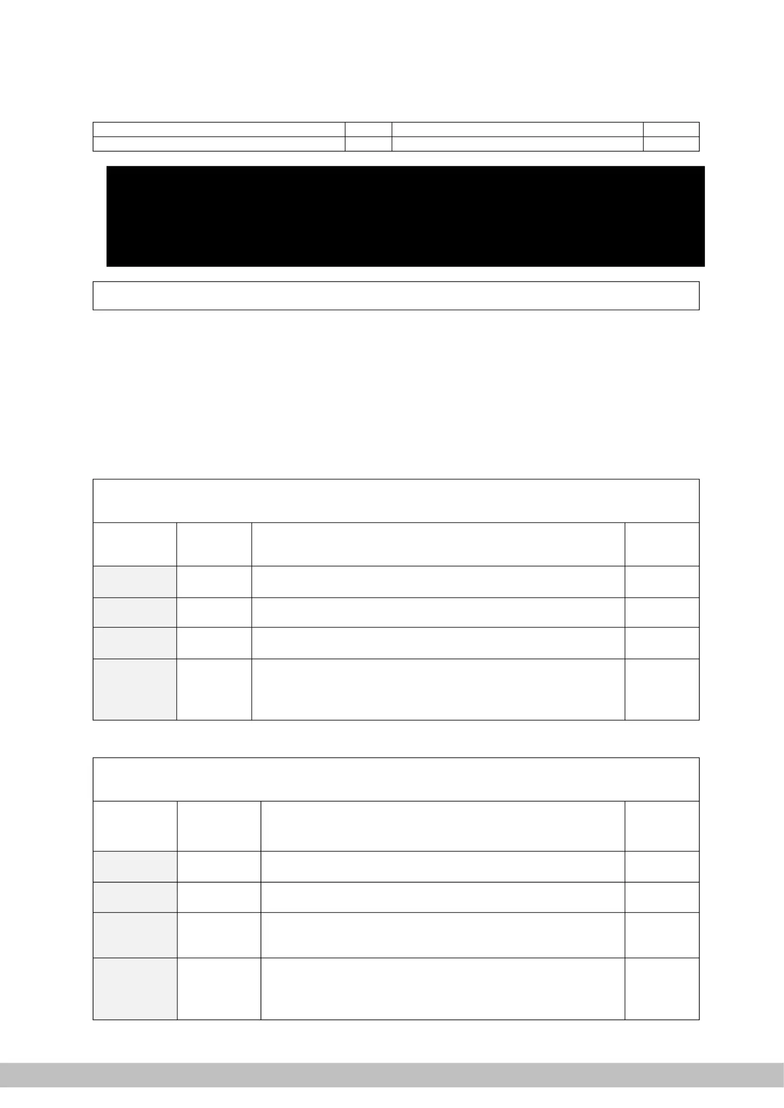
1 BOILER CONFIGURATION
Table 1, inserts and associated gas ring for conversion to G31
Gas category:
Propane P
G31 /50 mBar, 30/37
Article no.
conv. set
Insert model
Applicable for boiler models
Gas ring
EKPS075917
541
EHOB12AAV1, EHOBG12AAV1
RHOB12AAV1, RHOBG12AAV1
315
EKPS075877
471
EHOBG18AAV1, EKOMBG22AAV1, EKOMBGU22AAV1,
RHOBG18AAV1, RKOMBG22AAV1
410
EKPS075867
406
EHOB18AAV1, EKOMB22AAV1, EKOMBG28AAV1, EKOMBGU28AAV1
RHOB18AAV1, RKOMB22AAV1, RKOMBG28AAV1
480
EKHY075787
362
EKOMB28AAV1, EKOMB33AAV1, EKOMBG33AAV1, EHOB42AAV1
EKOMBGU33AAV1
RKOMB28AAV1, RKOMB33AAV1, RKOMBG33AAV1, RHOB42AAV1
EHYKOMB33AA, RHYKOMB33AA
525
Table 2, inserts and associated gas ring for conversion to G25
Gas category
Natural gas H
G25 25 mBar,
Article no.
conv. set
Insert model
Applicable for boiler models
Gas ring
EKPS076197
541
EHOB12AAV1, EHOBG12AAV1
RHOB12AAV1, RHOBG12AAV1
620
EKPS076207
471
EHOBG18AAV1, EKOMBG22AAV1, EKOMBGU22AAV1,
RHOBG18AAV1, RKOMBG22AAV1
550
EKPS076217
406
EHOB18AAV1, EKOMB22AAV1, EKOMBG28AAV1,
EKOMBGU28AAV1
RHOB18AAV1, RKOMB22AAV1, RKOMBG28AAV1
650
EKPS076227
362
EKOMB28AAV1, EKOMB33AAV1, EKOMBG33AAV1, EHOB42AAV1
EKOMBGU33AAV1
RKOMB28AAV1, RKOMB33AAV1, RKOMBG33AAV1, RHOB42AAV1
EHYKOMB33AA, RHYKOMB33AA
720
EKHY075787 / EK 075867 / EK 075877 / EK 075917 PS PS PS
EKPS076197 / EKPS 076207 / EKPS076217 / EKPS076227
Conversion Instructions
2 CONVERSION OF THE GAS RING
1. Switch off the electrical supply to the appliance
2. Close the gas tap on the gas supply to the appliance
3. Remove the front panel of the appliance
4. Disconnect the coupling above the gas valve and turn the gas mixing pipe backwards
5. Replace the original O-ring and the gas setting ring with the rings the conversion set in
6. Reconnect the coupling above the gas valve and open the gas tap
7. Check the gas connections for tightness/leaks
8. Switch on the electrical supply to the appliance
CAUTION
It is not possible to adjust the CO
2
level at high setting.
When the CO
2
level at high setting is not within the prescribed
tolerance band please contact your local Daikin or Rotex dealer.
For adjusting CO
2
level at low setting see § 3 .
9. Apply a sticker “gas type” (2 pcs. included in the conversion set) to the nut at the upper side of
the gas valve
10. Apply the second sticker “gas type” to the appliance plate (lower left corner) in such a way that
the original data referring to the gas type is covered.
11. Continue with checking the CO
2
setting of the boiler. See § 3 .
CAUTION
Checking the CO
2
setting of the boiler must be executed with the
front panel removed.
The maximum deviation of the flue gas analyser that is allowed is
± 0,3%.
During the check the installation location must not be under the
influence of over- or und pressure situations. er
It is not possible to adjust the CO
2
value at maximum power..
When the value measured at maximum power falls without the
prescribed range the boiler has to be checked on gas tightness and
usage of the correct components, in particular the gas ring, the
insert and the fan.
When replacing parts that can affect combustion or conversion to
another gas type the CO
2
setting needs to be checked.
.
EKHY075787 / EK 075867 / EK 075877 / EK 075917 PS PS PS
EKPS076197 / EKPS 076207 / EKPS076217 / EKPS076227
Conversion Instructions
3 CHECKING AND ADJUSTING CO
2
SETTING
3.1 Checking flue gas at maximum power.
1. off. Make sure that ppliance is switched the a
[- is shown in service display. ] the
2. Remove the cap X of the flue gas sampling point on the adapter.
3. Position the measuring probe or the flue gas analyser into the sampling point.
Important
Ensure that the analyser start up procedure has been
finalized before placing the probe.
The probe needs to close the sampling point fully to ensure
an accurate measurement.
The end (tip) of the probe must be completely in the flue
gasses (in the middle of the flue pipe).
.
4. button Switch the appliance on with the .
5. Activate the test program for maximum output by simultaneously pressing the buttons
twice. and
A capital appears in the service display. H
Important
Make sure a capital is shown in the display to ensure the H
appliance to run at maximum power.
6. Wait until the reading of the flue gas analyser is stabilized (minimal 3 minutes).
7. Note the measured value : CO
2
(H).
CO
2
(H) measured = CO
2
value at maximum power
8. Check if the measured value is in accordance with the data noted in table 3.
Table 3 Limits CO:
2
(H) at maximum power (front panel removed)
Limits
Gas category
Natural gas
G 25
Propane 3P
G31
CO
2
[%]
CO
2
[%]
Maximum value
9.6
10.8
Minimum value
8.6
9.8
Important
A deviation at maximum power can not be adjusted with the gas
valve setting. When the value measured at maximum power is
outside the prescribed range the boiler has to be checked on gas
tightness and usage of the correct components, in particular the
gas ring, the insert and the fan.
9. Proceed performing the measurement and adjustment on minimum output (see § 3.2).
3.2 Adjusting CO
2
value minimum power at
Important
Work on gas carrying parts may only be carried out by a qualified
competent person.
Before adjusting the CO
2
value at minimum output the measurement of the maximum
output must be completed. The measured O2 or CO2 value at maximum output is
important for determining the correct value for the measurement at minimum output.
See § 3.1 for measuring at maximum output.


Produktspezifikationen

Marke: Daikin
Kategorie: Zentralheizungskessel
Modell: EKPS

Brauchst du Hilfe?

Wenn Sie Hilfe mit Daikin EKPS benötigen, stellen Sie unten eine Frage und andere Benutzer werden Ihnen antworten