Doepfer A-140-2 Bedienungsanleitung
Doepfer Nicht kategorisiert A-140-2
Lies die bedienungsanleitung für Doepfer A-140-2 (4 Seiten) kostenlos online; sie gehört zur Kategorie Nicht kategorisiert. Dieses Handbuch wurde von 25 Personen als hilfreich bewertet und erhielt im Schnitt 4.9 Sterne aus 2 Bewertungen. Hast du eine Frage zu Doepfer A-140-2 oder möchtest du andere Nutzer dieses Produkts befragen? Stelle eine Frage
Seite 1/4
A-140-2 Dual ADSR
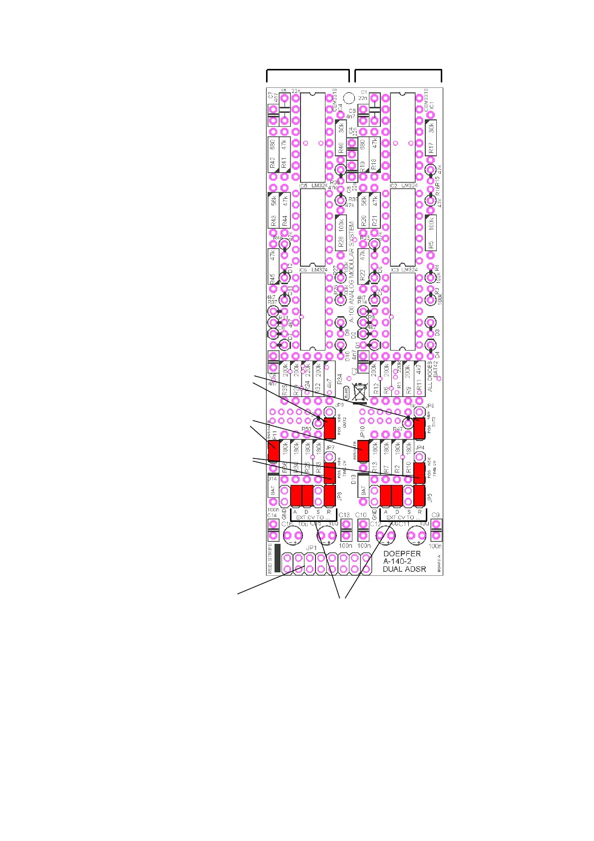
Position and function of the jumpers and connectors Board A
• The picture shows the factory setting of the jumpers.
• To change the polarity of the second output (Output 2) the position of JP6/JP9 has to be changed.
• To disconnect the unit from the gate signal on the bus JP11/JP10 has to be removed.
• To change the direction of the time control voltage CVT (i.e. if an increasing CV increases or decreases the
time parameters) the position of JP7/JP4 has to be changed
• If a parameter (A, D, R) should be removed from the CVT control the jumper in question has to be removed
• Normally Systain is not affected by CVT (as it's not a time parameter) and the corresponding jumper is not
installed in the factory. If voltage control of Sustain is desired the corresponding jumper has to be installed
on the position "S" of JP8/JP5.
JP11/JP10:
Bus Gate
JP9/JP6: Polarity of Output 2
upper position = inverted
lower position = non-inverted
JP7/JP4: Time CV Polarity
upper position = inverted
lower position = non-inverted
JP8/JP5: Time CV assignment
when jumper installed the corresponding
parameter (A, D, S, R) is CV controlled
JP1:
Bus Connecto
r
ADSR #2 ADSR #1
Produktspezifikationen
| Marke: | Doepfer |
| Kategorie: | Nicht kategorisiert |
| Modell: | A-140-2 |
Brauchst du Hilfe?
Wenn Sie Hilfe mit Doepfer A-140-2 benötigen, stellen Sie unten eine Frage und andere Benutzer werden Ihnen antworten
Bedienungsanleitung Nicht kategorisiert Doepfer

21 August 2024
21 August 2024
20 August 2024
20 August 2024
20 August 2024
20 August 2024
19 August 2024
19 August 2024
19 August 2024
19 August 2024
Bedienungsanleitung Nicht kategorisiert
Neueste Bedienungsanleitung für -Kategorien-
3 April 2026
3 April 2026
3 April 2026
3 April 2026
3 April 2026
3 April 2026
3 April 2026
3 April 2026
3 April 2026
3 April 2026