Extron FOX3 T 111 Bedienungsanleitung
Extron Nicht kategorisiert FOX3 T 111
Lies die bedienungsanleitung für Extron FOX3 T 111 (2 Seiten) kostenlos online; sie gehört zur Kategorie Nicht kategorisiert. Dieses Handbuch wurde von 4 Personen als hilfreich bewertet und erhielt im Schnitt 4.6 Sterne aus 7 Bewertungen. Hast du eine Frage zu Extron FOX3 T 111 oder möchtest du andere Nutzer dieses Produkts befragen? Stelle eine Frage
Seite 1/2
FOX3 T 111 • Setup Guide
IMPORTANT NOTE:
Go to www.extron.com for the complete FOX3 T 111 user guide, installation instructions, and specications
before connecting the product to the power source.
FOX3 T 111
This guide provides quick start instructions for an experienced installer to set up and operate the Extron FOX3 T 111 ber optic
transmitter.
WARNING: The FOX3 T 111 outputs continuous invisible light (Class 1 rated), which may be harmful to the eyes; use with
caution. Plug the attached dust caps into the optical transceivers when the ber cable is unplugged.
CLASS 1 LASER PRODUCT, see the FOX3 T 111 User Guide, at www.extron.com.
AVERTISSEMENT :Le FOX3 T 111 émet une lumière invisible en continu (conforme à la classe 1) qui peut être
dangereux pour les yeux, à utiliser avec précaution. Branchez les protections contre la poussière dans l’ensemble
émetteur/récepteur lorsque le câble bre optique est débranché.
Produit laser de classe 1, voir le FOX3 T 111 User Guide sur www.extron.com (en anglais).
Installation
Step 1 — Mounting
Turn o or disconnect all equipment power sources and mount the transmitter as required. For mounting details and
considerations, see the FOX3 T 111 User Guide at www.extron.com.
Step 2 — Input and Output Connections
OUTIN
POWER
12V
--
--
A MAX
INPUT
LOOP OUT
HDMI
A
FOX3 T 111
LAN
AAABBBCCCDDDEEE
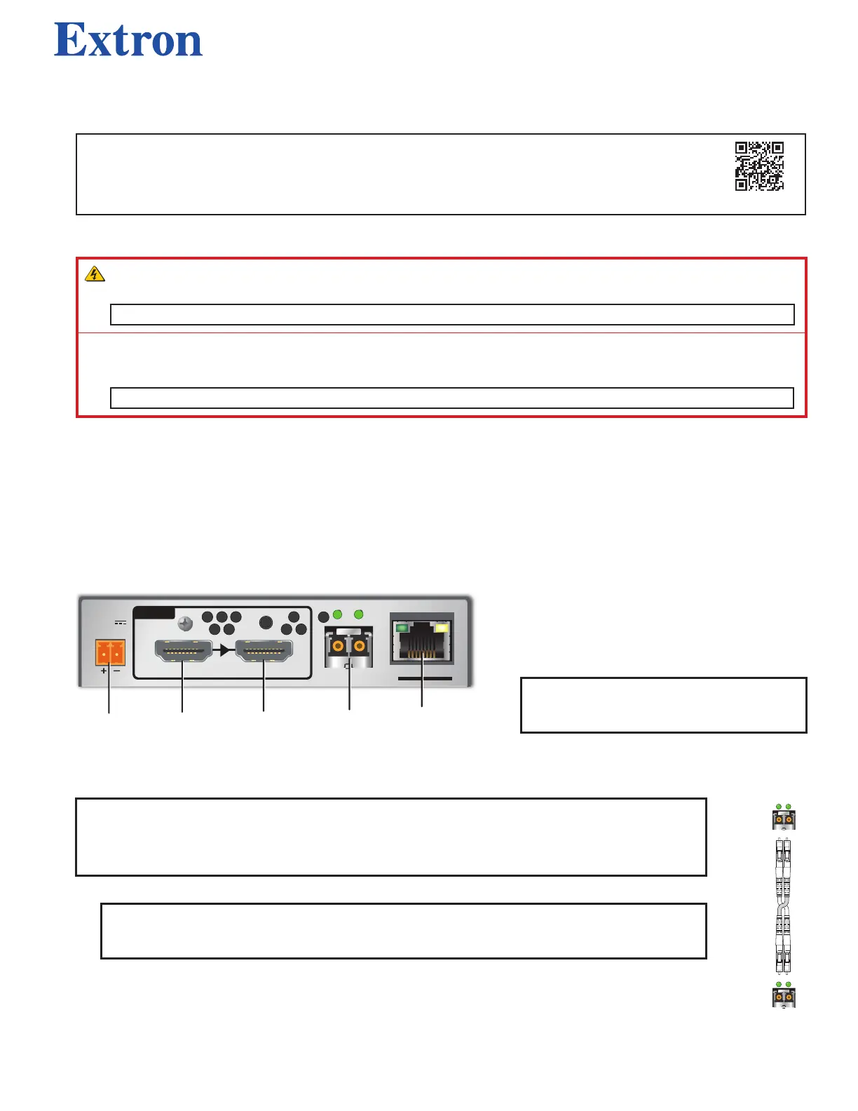
Figure 1. FOX3 T 111 Rear Panel
a. Connect an HDMI video source to the HDMI
input (see gure 1,
B
).
b. If desired, connect an HDMI video display to
the LOOP OUT port (
C
) on the transmitter for
a local display.
NOTE:See the FOX3 T 111 User Guide
to secure the HDMI connectors with the
enclosed LockIt Plus brackets.
Step 3 — Throughput Connections
NOTE:See the image on the right for ber cable connections. Connect the transmitter (
D
) to a receiver in
one of two ways:
• One way (transmitter to receiver) only, perform step 3a.
• Two way (transmitter to receiver and return), perform steps 3a and 3b.
a. Connect the ber between the transmitter AOut port and the receiver AIn port (
1
).
NOTE:Ensure that the transmitter and connected receiver are in the same transmission mode,
singlemode (SM) or multimode (MM), and use the correct SM or MM ber cable to connect the
devices.
b. To return serial data from the receiver to the transmitter, connect a cable between the receiver A Out port and
the transmitter A In port (
2
).
SFP Link LEDs —
Receiver
T
ransmitter
11
22
22
11
A
OUTIN
A
OUTIN
• Transmit Optical OUT LED lights solid green when powered and is o when there is no power on the endpoint.
• Receive Optical IN LED lights solid green when light is present and is o when there is no power or light present.
1
1
Produktspezifikationen
| Marke: | Extron |
| Kategorie: | Nicht kategorisiert |
| Modell: | FOX3 T 111 |
Brauchst du Hilfe?
Wenn Sie Hilfe mit Extron FOX3 T 111 benötigen, stellen Sie unten eine Frage und andere Benutzer werden Ihnen antworten
Bedienungsanleitung Nicht kategorisiert Extron

25 März 2026
28 Februar 2026
3 Februar 2026
2 Februar 2026
2 Februar 2026
25 November 2025
24 November 2025
11 November 2025
11 November 2025
7 Oktober 2025
Bedienungsanleitung Nicht kategorisiert
Neueste Bedienungsanleitung für -Kategorien-
3 April 2026
3 April 2026
3 April 2026
3 April 2026
3 April 2026
3 April 2026
3 April 2026
3 April 2026
3 April 2026
3 April 2026