Festo CASM-S-D3-R7 Bedienungsanleitung
Festo Nicht kategorisiert CASM-S-D3-R7
Lies die bedienungsanleitung für Festo CASM-S-D3-R7 (2 Seiten) kostenlos online; sie gehört zur Kategorie Nicht kategorisiert. Dieses Handbuch wurde von 34 Personen als hilfreich bewertet und erhielt im Schnitt 4.8 Sterne aus 6 Bewertungen. Hast du eine Frage zu Festo CASM-S-D3-R7 oder möchtest du andere Nutzer dieses Produkts befragen? Stelle eine Frage
Seite 1/2
Warnung, Warning, ..............................
deVerletzungsgefahr durch unkontrollierte Bewegungen
der Aktorik!
Schalten Sie vor Installations- und Wartungsarbeiten
die Energiequellen in folgender Reihenfolge ab:
1.Druckluftversorgung
2.Spannungsversorgung
enSudden uncontrolled movements of the actuators can
cause injury to human beings.
Before carrying out installation and/or maintenance
work, switch off the following sources of energy in the
sequence specified:
1.the compressed air supply
2.the power supply.
zh。
/,
!"#:
1.%&'()
2.*#。
S1
S2
Bild 1 / Fig. 1 / +, 1
4
5
6
123
Bild 2 / Fig. 2 / +, 2
777
Bild 3 / Fig. 3 / +, 3
Bild 4 / Fig. 4 / +, 4
8
S1
S2
Sensorinterfacede................................................
CASM-S-D3-R7
1Bestimmungsgemäße Verwendung
Das Sensorinterface CASM-S-D3-R7 dient bestimmungsge
mäß zur Anschaltung pneumatischer Antriebe mit digitalem,
inkrementalem Wegmesssystem an einen Positioniercontrol
ler von Festo (z. B. Typ CMAX oder CMPX).
Es stellt die Verbindung zwischen Wegmesssystem und einem
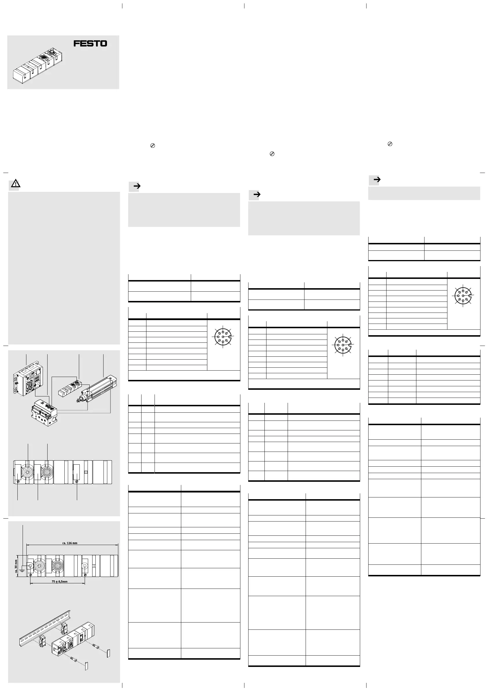
Proportional-Wegeventil VPWP her, siehe Bild 1:
1Positioniercontroller CMAX oder Soft Stop CMPX
2Proportional-Wegeventil VPWP
3Sensorinterface CASM-S-D3-R7
4Antrieb mit Wegmesssystem (digital, inkremental,
hier DNCI)
2Anschluss- und Anzeigeelemente
Siehe Bild 2:
5S1: Anschluss für VPWP (mit LED grün/rot)
6S2: Anschluss für Wegmesssystem (mit LED rot/gelb)
7Bezeichnungsschilder ISB-8x20 (Zubehör)
3Montage
Befestigen Sie den CASM-S-D3-R7 auf einer ebenen Fläche
mit zwei Schrauben M4 und jeweils einer Sicherungsscheibe,
siehe Bild 3.
Anziehdrehmoment: 2 ±0,5 Nm.
Das Symbol kennzeichnet die Lage der Befestigungs
schrauben. Die äußere Befestigungsschraube dient gleichzei
tig zur Erdung (
8 ).
Die Befestigung auf Hutschienen nach EN 60715 ist mit dem
Montagesatz Typ CP-TS-HS35 möglich, siehe Bild 4.
4Installation
Hinweis..................................................
Störungen durch elektromagnetische Einflüsse können die
Messergebnisse verfälschen und falsche Positionen
vortäuschen.
Beachten Sie die folgenden Hinweise, um Störungen
durch elektromagnetische Einflüsse zu vermeiden.
Verwenden Sie nur die Originalkabel (siehe Tabelle).
Verlängern Sie die Kabel nicht.
Ein Verlängern der Kabel senkt die Störfestigkeit.
Verlegen Sie die Kabel nicht in der Nähe oder parallel zu
Leitungen mit hohem Störpegel.
Fixieren Sie die Stecker mit Hilfe der Überwurfmutter.
Verbinden Sie den Erdungsanschluss ( 8 ) niederohmig
mit dem Erdpotenzial.
Verbindung zuVerbindungleitung Typ
Proportional-Wegeventil
VPWP-...
KVI-CP-3-...
Wegmesssystem Normzylinder DNCI
oder CDNI
Fest am Normzylinder ange
schlossen (Stecker M12)
Messsystem-Schnittstelle S2 ( 6 )
PinBelegungAnschluss S2
1+ Ub Sensor (5 V)
4
3
7
1
6
5
8
2
20 V
3Signal Sinus +
4Signal Sinus –
5Signal Cosinus –
6Signal Cosinus +
7Schirm
8n.c. (nicht verbunden)
GehäuseErdungsanschluss (FE)
Kabelschirm wird auf Erdungsanschluss des Sensorinterface geführt.
5Diagnose
LED
S1
LED
S2
Zustand
ausaus24 V nicht vorhanden
blinkt
grün
rot24 V vorhanden
grünrotInitialisieren über CAN abgeschlossen
grünausBetriebsbereit ohne Fehler
grünblinkt
rot 1x
Sensorfehler
grünblinkt
rot 2x
Kabelbruch Sensorkabel
grünblinkt
rot 3x
Versorgungsspannung < 17 V für länger als 15 ms
grünblinkt
rot 4x
CAN-Kommunikation gestört: Bus Off Zustand
6Technische Daten
Typ
CASM-S-D3-R7
Maße (ohne Stecker)Breite:ca. 30 mm
Höhe:ca. 34 mm
Länge:ca. 126 mm
Gewichtca. 130 g
Temperaturbereich:
–Betrieb
–Lagerung/Transport
-5 … +50 C
-20 … +70 C
Relative Luftfeuchtigkeit95 %, nicht kondensierend
Schutzart nach EN 60529IP65 und IP67 (angeschlossen)
Schockfestigkeit30 g Beschleunigung bei 11 ms
Dauer
Schwingfestigkeit Transport
Schwingfestigkeit Betrieb
3,5 mm Weg bei 2…9 Hz, 1 g Be
schleunigung bei 9…200 Hz
0,35 mm Weg bei 10…60 Hz,
5 g Beschleunigung bei 60…150 Hz
CE-Zeichen (siehe Konformität
serklärung)
1)
è www.festo.com
nach EU-EMV-Richtlinie
–Max. Leitungslänge30 m
Ventilanschluss
–Ausführung
–Spannungsversorgung
–Restwelligkeit
–Stromaufnahme bei Nenn
betriebsspannung
–Anforderungen an die Span
nungsversorgung Elektronik
M9 Anschluss, Stift, 5-polig
24 V
±25 %
4 Vss bei 50 Hz
45 mA
Netzteil gemäß PELV Richtlinie
Messsignalanschluss
–Ausführung
–Messverfahren
–Sensorversorgung
–Sensorsignale
M12 Anschluss,Dose, 8-polig
Inkrementale Wegmessung
5 V und GND
werden an 2 Magnetfeldsensoren
abgegriffen
Galvanische Trennung:
CAN-Bus/Messsignal
nein
1)Das Gerät ist für den Einsatz im Industriebereich vorgesehen.
Außerhalb von industriellen Umgebungen, z.B. in Gewerbe- und Wohn-
Mischgebieten, müssen evtl. Maßnahmen zur Funkentstörung getroffen
werden.
Sensor interfaceen..............................
CASM-S-D3-R7
1Designated use
The sensor interface CASM-S-D3-R7 has been designed to be
used for connecting pneumatic drives with incremental, digi
tal measuring system to a positioning controller from Festo
(e. g. type CMAX or CMPX).
It provides the connection between the measuring system and
a proportional directional control valve type VPWP, seeFig. 1:
1Positioning controller CMAX or Soft Stop CMPX
2Proportional directional control valve VPWP
3Sensor interface CASM-S-D3-R7
4Drive with measuring system (incremental, digital, here
DNCI)
2Connection and display elements
See Fig. 2:
5S1: Connection for VPWP (with green/red LED)
6S2: Connect. for measuring system (with red/yellow LED)
7Identification labels ISB-8x20 (accessories)
3Mounting
Fasten the CASM-S-D3-R7 on a flat surface with two M4
screws each with a retaining washer, see Fig. 3.
Tightening torque: 2 ±0.5 Nm.
The symbol
marks the position of the fastening screws.
The outer fastening screw serves at the same time for
earthing (
8 ).
Fastening on hat rails as per EN 60715 is possible with
mounting kit type CP-TS-HS35, see Fig. 4.
4Installation
Please note..............................................
Interference caused by electromagnetic influences can
falsify the measured results and simulate incorrect
positions.
Observe the following installation instructions in order
to avoid interference caused by electromagnetic
influences.
Use only the original cable (see table).
Do not extend the cables.
Extending the cables will reduce immunity to interference.
Do not place the cables near or parallel to cables with high
levels of interference.
Fasten the plugs with the aid of the union nut.
Connect the earthing connection (
8 ) at low impedance to
the earth potential.
Connection toCable type
Proport. direct. control valve
VPWP-...
KVI-CP-3-...
Measuring system standards-
based cylinders DNCI or CDNI
Permanently attached to stan
dards-based cylinder (M12 plug)
Measuring system interface S2 ( 6 )
PinAssignmentConnection S2
1+ Ub sensor (5 V)
4
3
7
1
6
5
8
2
20 V
3Signal sinus +
4Signal sinus –
5Signal cosinus –
6Signal cosinus +
7Screen
8n.c. (not connected)
HousingEarthing connection (FE)
The cable screening is connected to the earthing terminal of the
sensor interface.
5Diagnosis
LED
S1
LED
S2
Status
offoff24 V not available
flashes
green
red24 V available
greenredInitializing via CAN completed
greenoffReady to operate without fault
greenflashes
red once
Sensor fault (sensor voltage > 9.97 V or
< 0.03 V)
greenflashes
red twice
Sensor cable interrupted
greenflashes
red 3times
Supply voltage < 17 V for longer than 15 ms
greenflashes
red 4times
CAN communication interrupted: Bus Off
status
6Technical specifications
TypeCASM-S-D3-R7
Dimensions (without plug)width:approx. 30 mm
height:approx. 34 mm
length:approx. 126 mm
Weightsapprox. 130 g
Temperature range:
–Operation
–Storage/transport
0 … +55 C
-20 … +70 C
Relative air humidity95 %, non-condensing
Protection class as per EN60529IP65 and IP67 (connected)
Shock resistance30 g acceleration at 11 ms
duration
Resistance to vibration, transport
Resistance to vibration, operation
3.5 mm path at 2…9Hz,
1 g acceleration at 9…200 Hz
0.35 mm path at 10…60 Hz,
5 g acceleration at 60…150 Hz
CE marking (see declaration of
conformity)
1)
è www.festo.com/sp
in accordance with EU EMC
Directive
–Max. cable length30 m
Valve connection
–Design
–Power supply
–Residual ripple
–Current consumption at rated
operating voltage
–Requirements of the power
supply for the electronics
M9 connection, pin, 5-pin
24 V
±25 %
4 Vpp at 50 Hz
45 mA
power unit as per PELV
guideline
Measuring signal
–Design
–Measuring type
–Sensor supply
–Sensor signals
M12 connection, socket, 8 pin
Incremental position measuring
5 V and GND
are tapped at 2 magnetic field
sensors
Electrical isolation:
CAN bus/measuring signal
no
1)The device is intended for use in an industrial environment. Outside of
industrial environments, e.g. in commercial and mixed-residential
areas, actions to suppress interference may have to be taken.
德语...............................
CASM-S-D3-R7
1
-./ CASM-S-D3-R7
0123.(4567896:;,
Festo(=>? CMAX CMPX)。
AB96:;>? VPWP
CDEFG3.,HI+,。 1:
1 CMAX JK CMPX
2CDEF VPWP
3-./ CASM-S-D3-R7
496:;4(56L、78L,M DNCI)
2
HI+, 2:
5S1: 3. VPWP(NOP/QP LED)
6S2:3.96:;(NQP/RP LED)
7STSU ISB-8x20(V)
3
2NWX M4 YZ[ CASM-S-D3-R7
\]^,HI+, 3。
_`ab: 2 ±0.5 Nm.
c?Sd Sd`\YZe。
fg`\YZhi2.j (8).
2k>? CP-TS-HS35,l EN 60715
\mnopq,HI+, 4。
4
......................................................
*rst"uv96wxy,z{|e}~。
l*rst。
2*(HI,)。
*。
*[st"。
[*est*V]。
2.Yn\。
[.j3. (8) *3..j*。
CDEF VPWP-...KVI-CP-3-...
96:;S( DNCI
CDNI
V S(
(M12 )
S2 (6)
!" S2
1+Ub - (5 V)
4
3
7
1
6
5
8
2
20 V
3? +
4? –
5? –
6? +
7
83.
f.j3. (FE)
*3.-./.j。
5#$
LED S1LED S2%&
24 V 2
OPQP24 V 2
OPQPv CAN ¡¢
OP£¤¥,¦§¨©
OPQPª-¤¥
OPQPª-*!
OPQP 3 ª*#*% < 17 V «¬ 15 ms
OPQP 4 ªCAN !:®¯!°±²
6'*+,
CASM-S-D3-R7
³´(µ)¶·:¸ 30 mm
¹·:¸ 34 mm
º·:¸ 126 mm
»6¸ 130 g
¼·½¾:
–¼·
–¿/À
0 ... +55 °C
-20 ... +70 °C
Á'(·95 %,Ã
l EN 60529 ÄIP65 IP67(Å3.)
ÆÇÈ 11 ms 30 g É·
ÊÆ,À
ÊÆ,
3.5 mm ËÌ (2 ... 9Hz,
1 g É· (9 ... 200 Hz
0.35 mm ËÌ (10 ... 60 Hz,
5 g É· (60 ... 150 Hz
CeSÍ
(IÎÆÏ)1)
è
www.festo.com/sp
cÐÑ*rÒÆ
-ÓÔ¯º·30 м
F3.
–01
–*#
–ÕÖ
–×*%i*ØÙÚ
–*#*(ÛÜ
M9 3.、ÝÞ、5 ÝÞ
24 V
±25 %
4 Vpp (50 Hz)
45 mA
c PELV *#g
96?
–01
–96Ä>
–-*
–-?
M12 3.、ß、8 ÝÞ
56e96
5 V GND
.à 2 rá-
*âã:
CAN ®¯/96?
£
1)ä0§2åæ。
çèéf,=:êëìí,îïðñòó
£¯*st。
CASM-S-D3-R7
Kurzbeschreibung
Brief description
ôõ
Original: de
Festo SE& Co. KG
Postfach
D-73726 Esslingen
Phone:
+49/711/347-0
www.festo.com
8043270
1505a
[8043271]
Produktspezifikationen
| Marke: | Festo |
| Kategorie: | Nicht kategorisiert |
| Modell: | CASM-S-D3-R7 |
Brauchst du Hilfe?
Wenn Sie Hilfe mit Festo CASM-S-D3-R7 benötigen, stellen Sie unten eine Frage und andere Benutzer werden Ihnen antworten
Bedienungsanleitung Nicht kategorisiert Festo

1 August 2025
1 August 2025
1 August 2025
1 August 2025
1 August 2025
1 August 2025
1 August 2025
1 August 2025
1 August 2025
1 August 2025
Bedienungsanleitung Nicht kategorisiert
Neueste Bedienungsanleitung für -Kategorien-
3 April 2026
3 April 2026
3 April 2026
3 April 2026
3 April 2026
3 April 2026
3 April 2026
3 April 2026
3 April 2026
3 April 2026