Festo CPE18-PRSGO-2 Bedienungsanleitung
Festo Nicht kategorisiert CPE18-PRSGO-2
Lies die bedienungsanleitung für Festo CPE18-PRSGO-2 (2 Seiten) kostenlos online; sie gehört zur Kategorie Nicht kategorisiert. Dieses Handbuch wurde von 5 Personen als hilfreich bewertet und erhielt im Schnitt 4.9 Sterne aus 3 Bewertungen. Hast du eine Frage zu Festo CPE18-PRSGO-2 oder möchtest du andere Nutzer dieses Produkts befragen? Stelle eine Frage
Seite 1/2
CPE...-PRS
Connection block
Festo SE & Co. KG
Ruiter Straße 82
73734 Esslingen
Deutschland
+49 711 347-0
www.festo.com
Operating instructions
8151076
2021-03g
[8151078]
Translation of the original instructions
© 2021 all rights reserved to Festo SE & Co. KG
1
Applicable documents
All available documents for the product
è
www.festo.com/sp.
2Safety
Safety instructions
Only use the product in original status without unauthorised modifications.
Intended use
The manifold blocks CPE...- PRS connect directional control valves to central
supply ports and are intended for wall or H-rail mounting.
3
Additional information
–Accessories
è
www.festo.com/catalogue.
4
Product overview
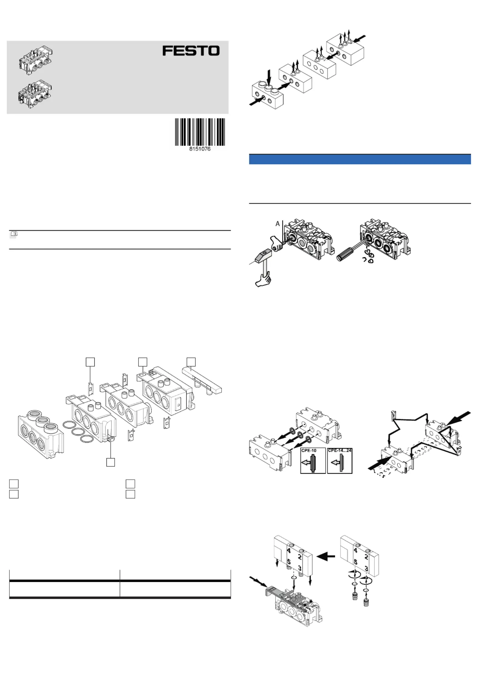
Structure
1
23
4
Fig.1
1
Connecting component
2
Valve spool
3
Blind plate
4
Mounting slide
Function
The manifold block CPE...-PRSG-2/-3 (double or triple) connects type CPE 5/2- or
5/3-way valves to central supply ports.
Two additional valves can be supplied with the help of the extension plate CPE...-
PRS-2.
The end plate CPE...-PRS-EP can be used to create different pressure zones or a
two-sided compressed-air supply.
The maximum configuration level is:
6 valves12 valves
–
with one-sided compressed-air supply or
–for every pressure zone
–
with two-sided compressed-air supply
Tab. 1
The CPE-...-PRSO-... have the diaphragms removed.
5Assembly
Preparation
Fig.2
1.Place all manifold blocks in their assembly sequence.
2.Trace the pressure curve, e.g. with a sketch.
When using multiple pressure zones:
NOTICE
•Make sure that the diaphragms at the interface of two pressure zones remain
intact.
Pressed-in diaphragms cannot be closed again. In doing so, consider
removing the diaphragms of the compressed air ducts for an unobstructed
flow rate.
Removing unused diaphragms:
Fig.3
1.
Press in the 3 diaphragms of the compressed air ducts on the manifold block
from the outside inwards in accordance with the pressure curve sketch using
a punch (A)
2.
Deburr fracture margins and
3.
Remove chips.
This time-saving method of operation results in irregular broken edges compared
to precision machining.
Assembly
H-rail mounting:
1.
Place all manifold blocks on the H-rail in accordance with the assembly
sequence.
2.
Press the manifold blocks on the H-rail until the mounting slides engage.5
Linking manifold blocks:
Fig.4
1.
Place one sealing ring each between each of the three compressed air ducts
and press the manifold blocks together.
2.
Push a connecting component onto the rail shown on both sides until it1
clicks into place.
Mounting the CPE valves:
Fig.5
1.Insert all valve spools up to the first detent.2
2.
Place a seal on every compressed air outlet.
Produktspezifikationen
| Marke: | Festo |
| Kategorie: | Nicht kategorisiert |
| Modell: | CPE18-PRSGO-2 |
Brauchst du Hilfe?
Wenn Sie Hilfe mit Festo CPE18-PRSGO-2 benötigen, stellen Sie unten eine Frage und andere Benutzer werden Ihnen antworten
Bedienungsanleitung Nicht kategorisiert Festo

1 August 2025
1 August 2025
1 August 2025
1 August 2025
1 August 2025
1 August 2025
1 August 2025
1 August 2025
1 August 2025
1 August 2025
Bedienungsanleitung Nicht kategorisiert
Neueste Bedienungsanleitung für -Kategorien-
3 April 2026
3 April 2026
3 April 2026
3 April 2026
3 April 2026
3 April 2026
3 April 2026
3 April 2026
3 April 2026
3 April 2026