Festo DADP-SP-G9-6-R Bedienungsanleitung
Festo Nicht kategorisiert DADP-SP-G9-6-R
Lies die bedienungsanleitung für Festo DADP-SP-G9-6-R (2 Seiten) kostenlos online; sie gehört zur Kategorie Nicht kategorisiert. Dieses Handbuch wurde von 36 Personen als hilfreich bewertet und erhielt im Schnitt 5.0 Sterne aus 7 Bewertungen. Hast du eine Frage zu Festo DADP-SP-G9-6-R oder möchtest du andere Nutzer dieses Produkts befragen? Stelle eine Frage
Seite 1/2
DADP-SP-G9-...-R
Sub-base kit
Festo SE & Co. KG
Ruiter Straße 82
73734 Esslingen
Germany
+49 711 347-0
www.festo.com
Assembly instructions
8195137
2023-07a
[8195139]
8195137
Translation of the original instructions
© 2023 all rights reserved to Festo SE & Co. KG
1
Applicable documents
All available documents for the product
è
www.festo.com/sp.
DocumentProductContents
Operating instructionMini slide DGSS–
Operating instructionShock absorber DYEF, DYSS–
Tab. 1:
Applicable documents
2Safety
2.1
Safety instructions
–Only mount the product on components that are in a condition to be safely
operated.
2.2Intended use
The sub-base kit in combination with two shock absorbers on the mini slide DGSS
cushions its extended and retracted end position. The sub-base contains the axial
air connections for the mini slide.
3
Additional information
–Contact the regional Festo contact if you have technical problems
è
www.festo.com.
–Accessories
è
www.festo.com/catalogue.
4
Product Range Overview
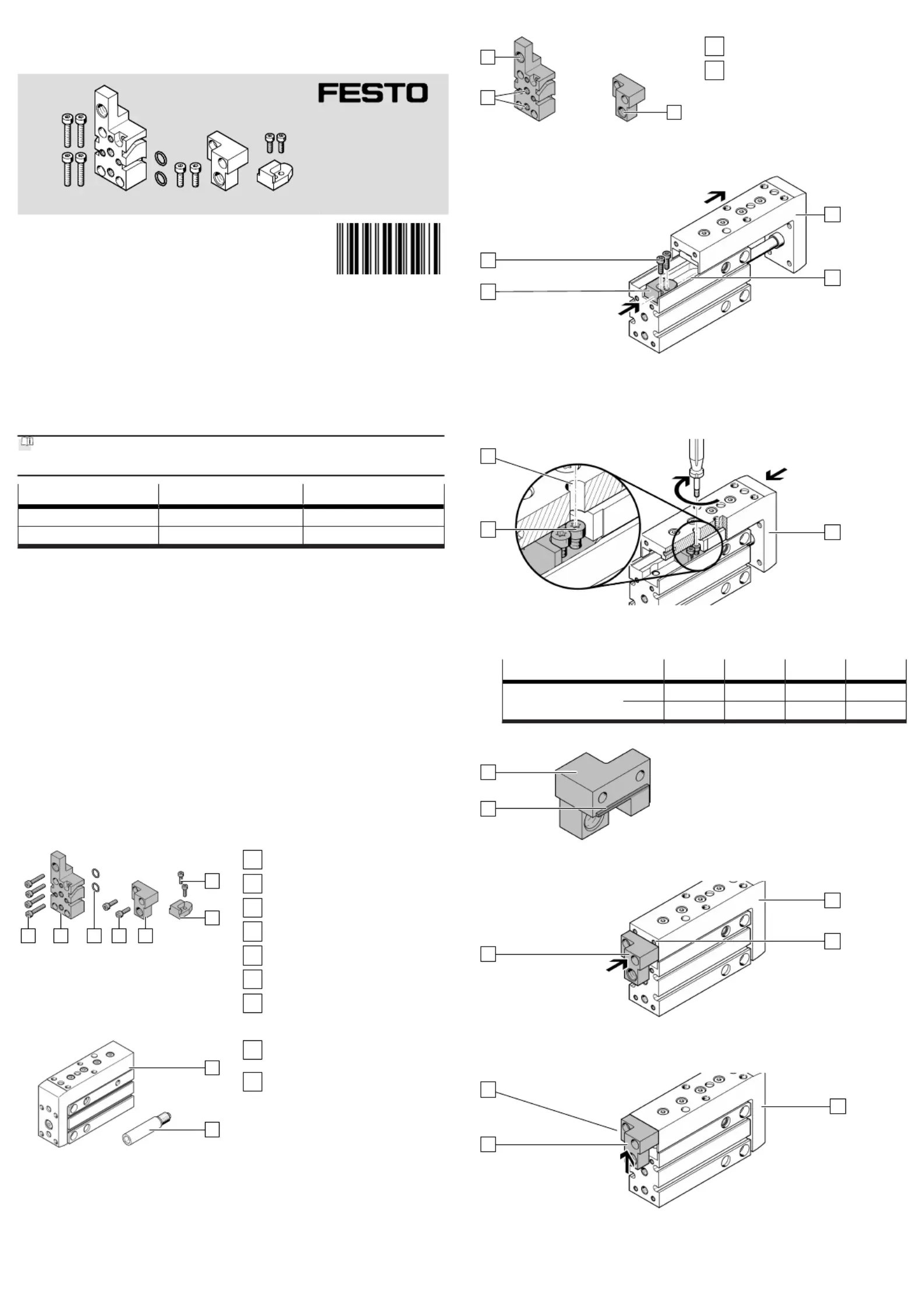
4.1Scope of delivery
1
2
35674
Fig.1
1
Screw (2x)
2
Stop (1x)
3
Stop element (1x)
4
Screw (2x)
5
O-ring (2x)
6
Connecting plate (1x)
7
Screw (4x)
4.2
Not in scope of delivery
8
9
Fig.2
8
Mini slide (1x)
DGSS
9
Shock absorber (2x)
DYEF-G8/DYSS-G8
5Product design
Z
Z
Y
Fig. 3:Product design
Y
Axial air connections
Z
Thread for shock absorber
6Assembly
1
A
B
2
Fig. 4:Pushing in stop
1.Extend the slide[A] manually.
2.Slide the stop into the slot[B].2
3.
Insert the screws into the holes of the stop.12
4.
Slide the stop to the end of the slot[B].2
A
C
1
Fig. 5:
Mounting stop
1.
Position the slide[A] so hole[C] is aligned with a screw.1
2.
Tighten the screw. Observe the tightening torque.1
DADP-SP-G9-6-10-16-20
ScrewM2 x 6M2.5 x 8M2.5 x 8M3 x 12
[Nm]0.3 ±15%0.5 ±15%0.7 ±15%0.9 ±15%
3.
Repeat this process for the second screw.1
C
3
Fig. 6:
Note the stop bar
•When installing the stop element, note the position of the stop bar[C].3
3
D
A
Fig. 7:
Aligning stop element
1.Retract the slide[A] manually.
2.
Position the upper edge of the stop element at the level of the thread[D].3
3
A
C
Fig. 8:
Attaching stop bar
1.Push the stop element upwards to the stop.3
Ä
The stop bar[C] is in contact with the slide[A].
2.Hold this position.
Produktspezifikationen
| Marke: | Festo |
| Kategorie: | Nicht kategorisiert |
| Modell: | DADP-SP-G9-6-R |
Brauchst du Hilfe?
Wenn Sie Hilfe mit Festo DADP-SP-G9-6-R benötigen, stellen Sie unten eine Frage und andere Benutzer werden Ihnen antworten
Bedienungsanleitung Nicht kategorisiert Festo

1 August 2025
1 August 2025
1 August 2025
1 August 2025
1 August 2025
1 August 2025
1 August 2025
1 August 2025
1 August 2025
1 August 2025
Bedienungsanleitung Nicht kategorisiert
Neueste Bedienungsanleitung für -Kategorien-
3 April 2026
3 April 2026
3 April 2026
3 April 2026
3 April 2026
3 April 2026
3 April 2026
3 April 2026
3 April 2026
3 April 2026