Festo MS6-EE-1/2-V24-B Bedienungsanleitung
Festo Nicht kategorisiert MS6-EE-1/2-V24-B
Lies die bedienungsanleitung für Festo MS6-EE-1/2-V24-B (2 Seiten) kostenlos online; sie gehört zur Kategorie Nicht kategorisiert. Dieses Handbuch wurde von 7 Personen als hilfreich bewertet und erhielt im Schnitt 4.5 Sterne aus 4 Bewertungen. Hast du eine Frage zu Festo MS6-EE-1/2-V24-B oder möchtest du andere Nutzer dieses Produkts befragen? Stelle eine Frage
Seite 1/2
MS6-EE-...-B
On/off valve
Festo SE & Co. KG
Ruiter Straße 82
73734 Esslingen
Germany
+49 711 347-0
www.festo.com
Operating instruction
8181863
2023-02a
[8181865]
8181863
Translation of the original instructions
© 2023 all rights reserved to Festo SE & Co. KG
1
Applicable documents
All available documents for the product
è
www.festo.com/sp.
DocumentProductContents
Assembly instructionsWall mounting kit MS...-WPE(-B)–
Tab. 1:
Applicable documents
2Safety
2.1Safety instructions
–
Only use the product in its original condition without unauthorised modifica-
tions.
–Only use the product if it is in perfect technical condition.
–
Observe the identifications on the product.
–Take into account the ambient conditions at the location of use.
–Before working on the product, switch off the compressed air supply and lock it
to prevent it from being switched on again.
2.2
Intended use
The on-off valve pressurises and exhausts pneumatic systems. The on/off valve is
not suitable for continuous switching operation for pneumatic components.
3
Additional information
–Accessories
è
www.festo.com/catalogue.
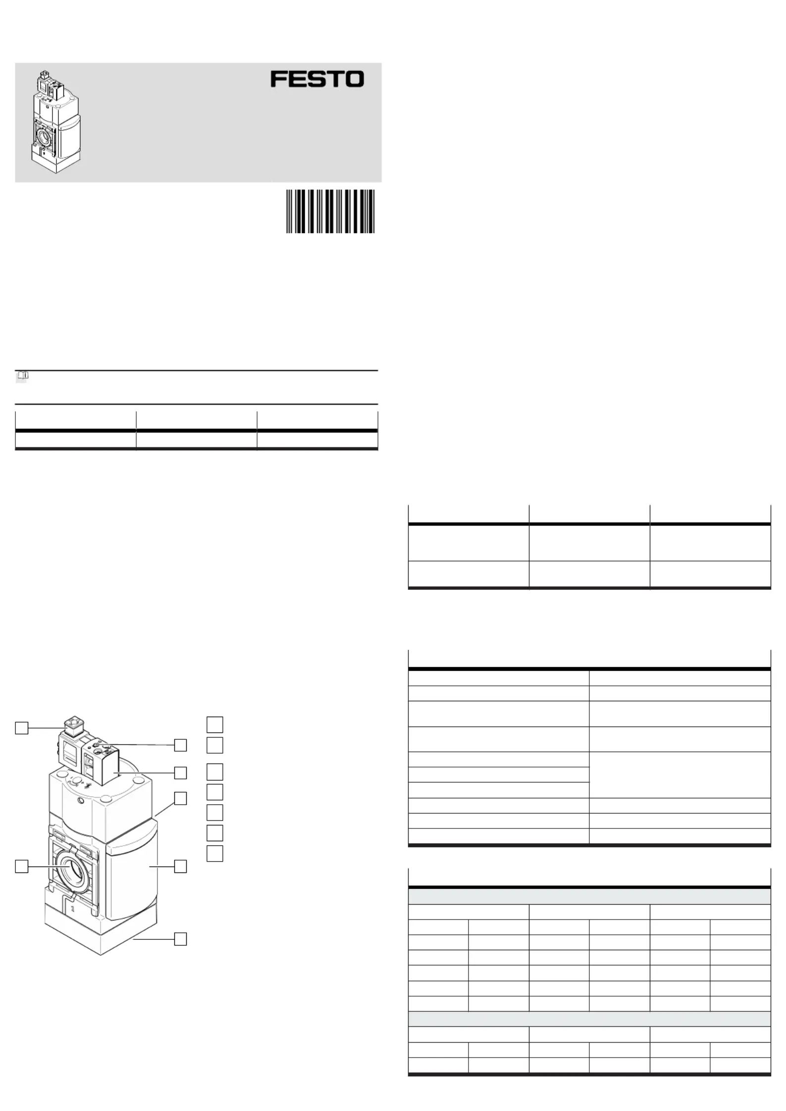
4Product design
1
2
3
4
6
5
7
Fig. 1:
Product design
1
Pneumatic port P1
2
Solenoid coil plug
(not in scope of delivery)
3
Manual override
4
Pilot valve
5
Pneumatic port P2
6
Orifice
7
Pneumatic port P3
5
Assembly
5.1Preparing assembly
For use with reduced particle emission:
•Remove soil from the product.
5.2Wall mounting
–
Space required above the product: 250mm³
–Space required under the product: 100mm³
–Space required left and right of the product: 30mm³
–
Shut-off valves are installed in the compressed air supply line.
•Fasten the product to the mounting surface with the mounting accessories
è
3 Additional information.
6Installation, pneumatic
1.Screw the fittings into the pneumatic ports.
2.Note the maximum screw-in depth of the connector thread. Screwing in
deeper will reduce the flow rate and can damage the housing. Maximum
screw-in depth:13.5mm
3.Insert suitable tubing into the fitting to the stop.
–
Position tubing axial to the pneumatic ports.
–Do not bend the tubing more than the minimum bending radius.
7
Commissioning
1.Screw the silencers into pneumatic port P3 to the stop. Suitable silencers7
è
3 Additional information.
2.
Mount the solenoid coil plug on the pilot valve. Suitable plugs2
è
3 Additional information.
3.Pressurise the system.
4.Switch the pilot valve.4
–
The product can also be switched on and off with the integrated manual
override.
Ä
There is pressure at pneumatic port P2.
5.
When the pilot valve is switched off, the system is exhausted via pneu-4
matic port P3.7
8Cleaning
•
Clean the outside of the product as required with a soft cloth.
Permissible cleaning agents:
–Soap solution, maximum +60°C
–
Petroleum ether, free of aromatic compounds
9Fault clearance
MalfunctionCauseRemedy
Low flow rate (operating pres-
sure is lost with air consump-
tion).
Constriction in the supply line.
–
Check the line.
Continuous audible blowing off
at the exhaust outlet.
The valve seat is damaged.
–
Replace the product.
Tab. 2:
Fault clearance
10Technical data
10.1
Technical data, mechanical
MS6-EE-...-B
Mounting position[°]Vertical±5
Manual overrideNon-detenting and detenting
Vibration resistance in accordance with
IEC60068-2-6
Severity level 2
Shock resistance in accordance with
IEC60068-2-27
Severity level 2
Pneumatic port P1G1/2
Pneumatic port P2
Pneumatic port P3
Temperature of medium[°C]–5…+50
Ambient temperature[°C]–5…+50
Storage temperature[°C]–10…+60
Tab. 3:
Technical data, mechanical
Type of severity level (SL)
Vibration load
Frequency range [Hz]Acceleration [m/s
2
]
Deflection [mm]
SL1SL2SL1SG2SL1SL2
2828––3.53.5……±±
8278271010––……
27582760––0.150.35……±±
58160601602050––……
1602001602001010––……
Shock load
Acceleration [m/s
2
]
Duration [ms]Shocks per direction
SL1SL2SL1SL2SL1SL2
±±150300111155
Produktspezifikationen
| Marke: | Festo |
| Kategorie: | Nicht kategorisiert |
| Modell: | MS6-EE-1/2-V24-B |
Brauchst du Hilfe?
Wenn Sie Hilfe mit Festo MS6-EE-1/2-V24-B benötigen, stellen Sie unten eine Frage und andere Benutzer werden Ihnen antworten
Bedienungsanleitung Nicht kategorisiert Festo

1 August 2025
1 August 2025
1 August 2025
1 August 2025
1 August 2025
1 August 2025
1 August 2025
1 August 2025
1 August 2025
1 August 2025
Bedienungsanleitung Nicht kategorisiert
Neueste Bedienungsanleitung für -Kategorien-
3 April 2026
3 April 2026
3 April 2026
3 April 2026
3 April 2026
3 April 2026
3 April 2026
3 April 2026
3 April 2026
3 April 2026