Festo SDBT-BSW-1L-ZU-W-5-N-LE Bedienungsanleitung
Festo Nicht kategorisiert SDBT-BSW-1L-ZU-W-5-N-LE
Lies die bedienungsanleitung für Festo SDBT-BSW-1L-ZU-W-5-N-LE (1 Seiten) kostenlos online; sie gehört zur Kategorie Nicht kategorisiert. Dieses Handbuch wurde von 20 Personen als hilfreich bewertet und erhielt im Schnitt 4.6 Sterne aus 4 Bewertungen. Hast du eine Frage zu Festo SDBT-BSW-1L-ZU-W-5-N-LE oder möchtest du andere Nutzer dieses Produkts befragen? Stelle eine Frage
Seite 1/1
Translation of the original instructions
© 2020 all rights reserved to Festo SE & Co. KG
1Applicable Documents
All available documents for the product www.festo.com/sp.è
2Safety
2.1Safety
–Before working on the electrics: switch off the voltage supply.
WARNING!
Risk of injury due to electric shock.
•For the electric power supply, use only PELV circuits that ensure a reliable
electric disconnection from the mains network.
•Observe IEC60204-1/EN60204-1.
2.2Intended use
This product is intended for sensing the position of magnets (e.g. the piston posi-
tion) in Festo products. The device is intended for use in an industrial environ-
ment.
2.2.1Area of application and approval
In combination with the UL inspection mark on the product, the information in this
section must also be observed in order to comply with the certification conditions
of Underwriters Laboratories Inc. (UL) for USA and Canada.
UL approval information
Product category codeNRKH, NRKH7
File numberE232949
Considered standardsUL 60947-1, CAN/CSA C22.2 No. 60947-1
UL 60947-5-2, CAN/CSA C22.2 No. 60947-5-2
UL mark
Industrial Control Equipment
2MD1
Tab. 1
Only for connection to a NEC/CEC Class 2 supply.
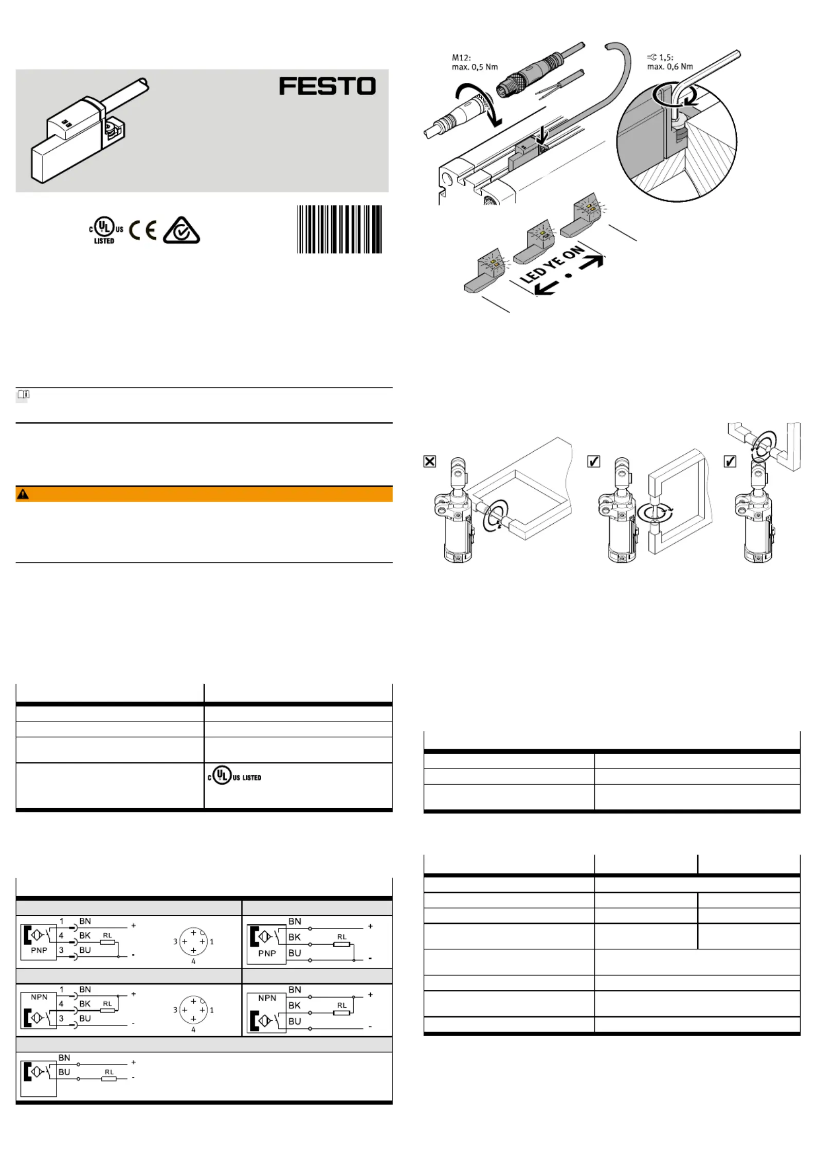
3Electrical connection
Circuit diagrams
SDBT-BSW-…-PU-…-M12SDBT-BSW-…-PU-…-LE
SDBT-BSW-…-NU-…-M12SDBT-BSW-…-NU-…-LE
SDBT-BSW-…-ZU-…-LE
Tab. 2
4Mechanical installation
Fig. 1 Mechanical installation
5Operating conditions
If the SDBT-BSW-...-PU or SDBT-BSW-...-NU is aligned at a right angle to the weld-
ing electrode or cable, it can result in maloperations in a limited range (applica-
tion-dependent).
Fig. 2 Operating conditions
Possible remedy:
–Adjust the distance between the proximity sensor and the source of malfunc-
tion (±20mm).
–Adjust the angle between the proximity sensor and the source of malfunction
(±20°).
–Adjust the strength of the welding current.
–On DW/DWA/DWB cylinders: mount sensor in a different position.
6Technical data
6.1Technical data UL
SDBT-BSW-…
Operating voltage range[VDC]10…30
Ambient temperature[°C]–25…+80
NEMA enclosure type number
(Enclosure Type Rating)
Type 1
Tab. 3
6.2Technical data, general
SDBT-BSW--PU/NUZU…
Operating voltage range[VDC]10…30
Max. output current[mA]10080
Max. switching capacity[W]2.81.9
Frequency of welding process
MFDC
[Hz]1000–
Frequency of welding process
AC
[Hz]50…60
Ambient temperature[°C]–25…+85
Ambient temperature with flex-
ible cable installation
[°C]–5…+80
Degree of protectionIP65, IP68
Tab. 4
8140618
SDBT-BSW-...
Proximity sensor
8140618
2020-07c
[8140620]
Operating instructions
Festo SE & Co. KG
Ruiter Straße 82
73734 Esslingen
Germany
+49 711 347-0
www.festo.com
Produktspezifikationen
| Marke: | Festo |
| Kategorie: | Nicht kategorisiert |
| Modell: | SDBT-BSW-1L-ZU-W-5-N-LE |
Brauchst du Hilfe?
Wenn Sie Hilfe mit Festo SDBT-BSW-1L-ZU-W-5-N-LE benötigen, stellen Sie unten eine Frage und andere Benutzer werden Ihnen antworten
Bedienungsanleitung Nicht kategorisiert Festo

1 August 2025
1 August 2025
1 August 2025
1 August 2025
1 August 2025
1 August 2025
1 August 2025
1 August 2025
1 August 2025
1 August 2025
Bedienungsanleitung Nicht kategorisiert
Neueste Bedienungsanleitung für -Kategorien-
3 April 2026
3 April 2026
3 April 2026
3 April 2026
3 April 2026
3 April 2026
3 April 2026
3 April 2026
3 April 2026
3 April 2026