Festo VABM-B10-20S-G14-5-P3 Bedienungsanleitung
Festo Nicht kategorisiert VABM-B10-20S-G14-5-P3
Lies die bedienungsanleitung für Festo VABM-B10-20S-G14-5-P3 (20 Seiten) kostenlos online; sie gehört zur Kategorie Nicht kategorisiert. Dieses Handbuch wurde von 31 Personen als hilfreich bewertet und erhielt im Schnitt 4.3 Sterne aus 7 Bewertungen. Hast du eine Frage zu Festo VABM-B10-20S-G14-5-P3 oder möchtest du andere Nutzer dieses Produkts befragen? Stelle eine Frage
Seite 1/20
Assembly instructions (Original instructions)
8067309
1701b
[8067311]
†‡
Connection block
VABM-B10-20S
Festo SE & Co. KG
Ruiter Straße 82
73734 Esslingen
Germany
+49 711 347-0
www.festo.com
1.Applicable documents
All available documents for the product www.f
esto.com/pk
2.Safety
Switch off compressed air before mounting work.
Observe tigh
tening torques.
3.Intended use
Pneumatic linking of the valves.
4.Further info
rmation
Accessories for VABM www.fes
to.com/catalogue
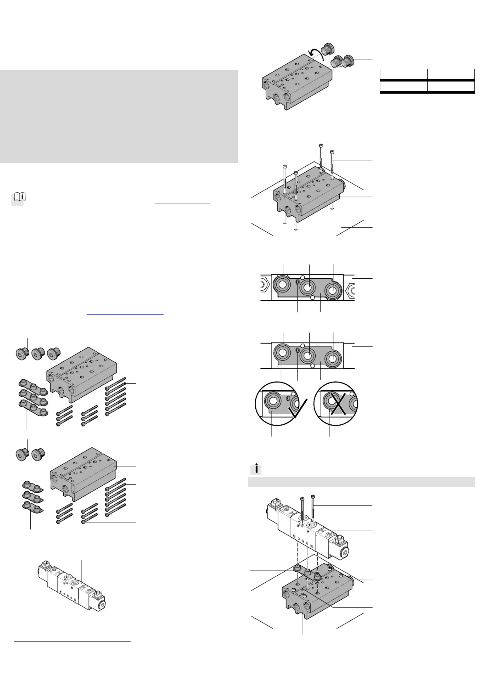
5.Scope of delivery
20272d_3
VABM-B10-20S-...
1Connection block
2Screw M3x40
1)2)
3Screw M3x30
1)2)
4Seal
1)
5Blanking plug B-1/4
(1x)
(nx)
(nx)
(nx)
(3x)
20272d_4
VABM-B10-20S-...-P3
1Connection block
2Screw M3x40
1)2)
3Screw M3x30
1)2)
4Seal
1)
5Blanking plug B-1/4
(1x)
(nx)
(nx)
(nx)
(2x)
6.Not in scope of delivery
20260d_3
6Solenoid valve
VUVS-… or
pneumatic valve
VUWS-...
1)
(nx)
1)
The number of screws , seals 23/4 and valves 6 is dependent on the available valve
positions.
2)
Number = 2 x available valve positions
7.Mounting of blanking plugs 5
5
5
55
20272d_9
Screw in the blanking
plugs 5 at the desired
position, as required.
Blanking plug [Nm]
58.5 _ 15 %
8.Mounting of connection b
l
ock 1
1
1
11
20272d_11
Place connection block 1
on mounting surface (A).
Tighten screws (B).
9.Alignment of seal 4
4
4
44
20272d_8
For valves VUVS-L/LT...:
Place the seal 4 in the
depression of the valve 6
so it is positive-locking.
Observe channel
designation 1/3/5 or 1/3.
20272d_12
For valves VUVS-LK...-S:
Place seal 4 on the
valve 6. Observe channel
designation 1/3/5 or 1/3.
Indexing hole (X) on the
valve 6 is:
–only relevant for the
connection block
VABM-B10-20S-...
–hidden according to the
alignment of the seal 4.
10.Mounting valve 6
6
6
66
Information
Screws 3 can only be mounted with solenoid valves 6 VUVS-LK…-S.
20272d_10
/Push screws 23 into the
drill holes of the valve 6.
Only screws 2 are
loss-protected.
Position valve 6 on the
connection block 1.
Check:
–Projection (C) is in the
slot (D)
–Valve 6 is aligned parallel
to the surface (E)
–Channel designations 1/3/5
or 1/3 agree with each
other.
Tighten screws 23/.
6
1.4 Nm _ 20 %
2
/
3
1
1
5
2
4
1
5
2
4
A
B
6
4
D
1
E
3
3
5
6
4
C
315
6
4
C
315
X
X
X
Produktspezifikationen
| Marke: | Festo |
| Kategorie: | Nicht kategorisiert |
| Modell: | VABM-B10-20S-G14-5-P3 |
Brauchst du Hilfe?
Wenn Sie Hilfe mit Festo VABM-B10-20S-G14-5-P3 benötigen, stellen Sie unten eine Frage und andere Benutzer werden Ihnen antworten
Bedienungsanleitung Nicht kategorisiert Festo

1 August 2025
1 August 2025
1 August 2025
1 August 2025
1 August 2025
1 August 2025
1 August 2025
1 August 2025
1 August 2025
1 August 2025
Bedienungsanleitung Nicht kategorisiert
Neueste Bedienungsanleitung für -Kategorien-
3 April 2026
3 April 2026
3 April 2026
3 April 2026
3 April 2026
3 April 2026
3 April 2026
3 April 2026
3 April 2026
3 April 2026