Festo VABM-B10-30-G34-6-P53 Bedienungsanleitung
Festo Nicht kategorisiert VABM-B10-30-G34-6-P53
Lies die bedienungsanleitung für Festo VABM-B10-30-G34-6-P53 (1 Seiten) kostenlos online; sie gehört zur Kategorie Nicht kategorisiert. Dieses Handbuch wurde von 33 Personen als hilfreich bewertet und erhielt im Schnitt 4.0 Sterne aus 2 Bewertungen. Hast du eine Frage zu Festo VABM-B10-30-G34-6-P53 oder möchtest du andere Nutzer dieses Produkts befragen? Stelle eine Frage
Seite 1/1
Assembly instructions (Original instructions)
8067428
1701c
[8067430]
†‡
Common supply manifold
VABM-B10-30-...-P53
Festo SE & Co. KG
Ruiter Straße 82
73734 Esslingen
Germany
+49 711 347-0
www.festo.com
1.Applicable documents
All available documents for the product www.f
esto.com/pk
2.Safety
Switch off compressed air before mounting work.
Observe tigh
tening torques.
3.Intended use
Pneuma
tic linking of the valves.
4.Further inf
o
rmation
Accessories for VABM www.fes
to.com/catalogue
5.Scope of delivery
21521d_1
VABM-B10-30-...-P53
1P manifold rail
2Blanking plug B-3/4
3Screw M5x60
1)2)
4Screw M5x40
1)2)
5Screw M5
(thread-cutting)
6Mounting bracket
7Seal
1)
8Distance ring
(1x)
(1x)
(nx)
(nx)
(8x)
(2x)
(nx)
(2x)
21521d_2
VABM-B10-30-...-P53-E
1P manifold rail
2Blanking plug B-3/4
3Screw M5x60
1)2)
4Screw M5x40
1)2)
5Screw M5
(thread-cutting)
6Mounting bracket
7Seal
1)
8Distance ring
(1x)
(1x)
(nx)
(nx)
(4x)
(1x)
(nx)
(1x)
6.Not in scope of d
e
livery
2148
1d
_9
9Solenoid valve
VUVS-... or
pneumatic valve
VUWS-...
1)
(nx)
2152
1d
_9
aJPush-in fitting (nx)
1)
The number of screws , seals 34/7 and valves 9 is dependent on the available valve
positions.
2)
Number = 2 x available valve positions
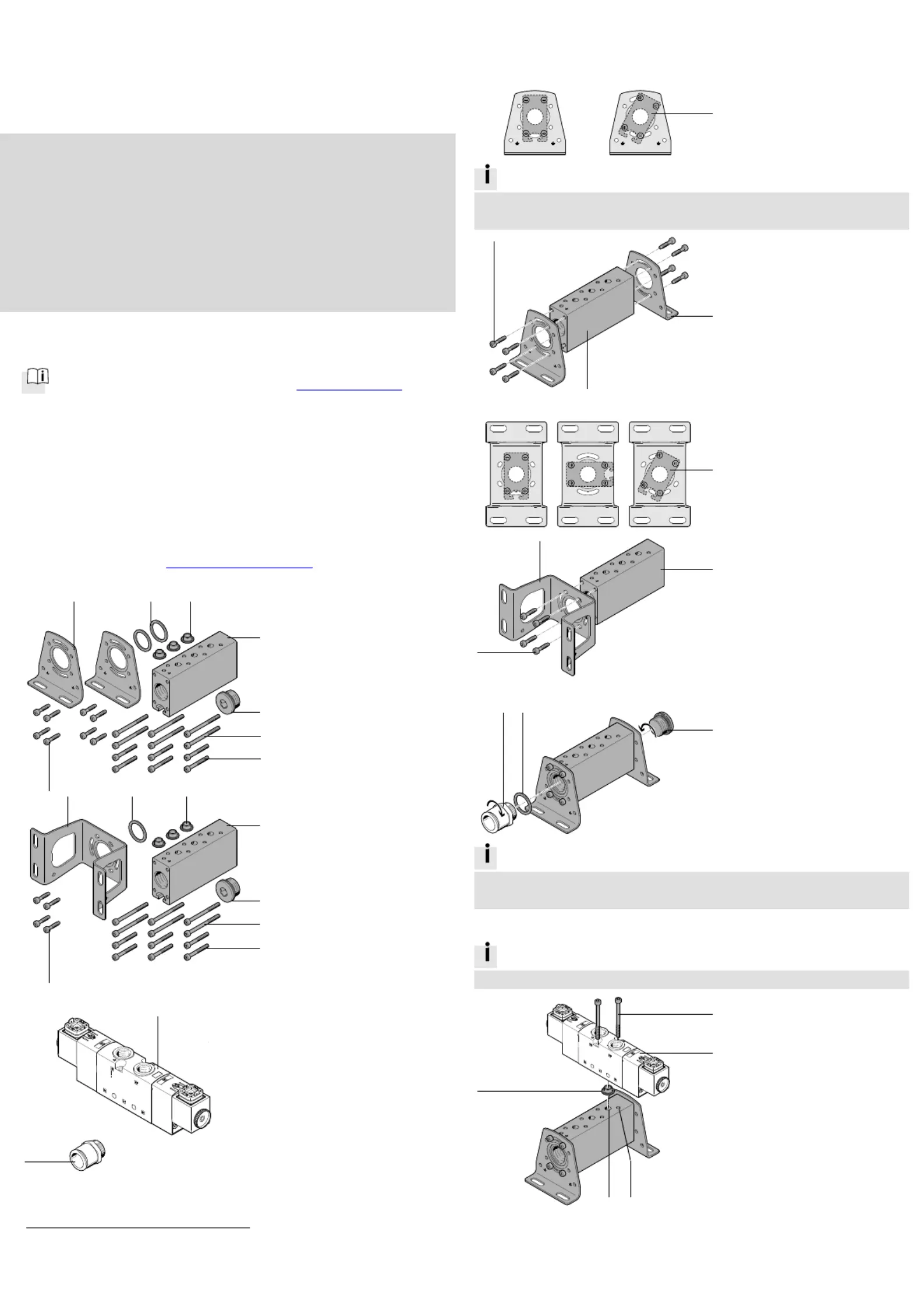
7.Mounting the mounting bracket 6
6
6
66
7a.VABM-B10-30-...-P53
2152
1d
_3
Define alignment of the
P manifold rail 1.
Information
The adjustment of the 0° and 30° angle of the common supply manifold 1
on a flat surface is dependent on the length of the silencer.
2152
1d
_5
Place both mounting
brackets 6 on the
P manifold rail 1.
Tighten all screws 5. If you
screw it in again, use the
threads already present.
7b.VABM-B
10-30-
...-P53-E
21521d_4
Define alignment of the
P manifold rail 1.
2152
1d
_6
Place the mounting
bracket 6 on the common
supply manifold 1.
Tighten all screws 5. If you
screw it in again, use the
threads already present.
8.Mounting the b
l
anking plug 2
2
2
22 and push-in fitting aJ
aJ
aJ
aJaJ
2152
1d
_7
Screw the blanking plug 2
in at the desired position,
as required.
Screw in the push-in
fitting aJ.
Information
One distance ring 8 each is required when mounting the push-in fittings
QS-G3/4-22 and CQ-3/4-22.
9.Mounting valve 9
9
9
99
Information
Screws 4 can only be mounted with solenoid valves 9 VUVS-LK…-S.
21521d_8
/Push screws 34 into the
drill holes of the valve 9.
Only screws 3 are
loss-p
r
otected.
Push seal 7 into channel 1
of the valve 9. Rotating
movement required during
mounting.
Place channel 1 of the
valve 9 onto the
opening (A).
Position the valve 9 on
the threads (B).
Tighten screws 34/.
1
1
2
2
3
3
5
5
7
7
6
6
9
3 Nm _ 20 %
3 Nm _ 20 %
6 Nm _ 20 %
3
/
4
6
5
1
1
5
6
9
7
AB
1
8
8
aJ
2
35 Nm
_ 10 %
8
aJ
1
4
4
Produktspezifikationen
| Marke: | Festo |
| Kategorie: | Nicht kategorisiert |
| Modell: | VABM-B10-30-G34-6-P53 |
Brauchst du Hilfe?
Wenn Sie Hilfe mit Festo VABM-B10-30-G34-6-P53 benötigen, stellen Sie unten eine Frage und andere Benutzer werden Ihnen antworten
Bedienungsanleitung Nicht kategorisiert Festo

1 August 2025
1 August 2025
1 August 2025
1 August 2025
1 August 2025
1 August 2025
1 August 2025
1 August 2025
1 August 2025
1 August 2025
Bedienungsanleitung Nicht kategorisiert
Neueste Bedienungsanleitung für -Kategorien-
3 April 2026
3 April 2026
3 April 2026
3 April 2026
3 April 2026
3 April 2026
3 April 2026
3 April 2026
3 April 2026
3 April 2026