Festo VAEM-S6-S-FAS-4-4E Bedienungsanleitung
Festo Nicht kategorisiert VAEM-S6-S-FAS-4-4E
Lies die bedienungsanleitung für Festo VAEM-S6-S-FAS-4-4E (2 Seiten) kostenlos online; sie gehört zur Kategorie Nicht kategorisiert. Dieses Handbuch wurde von 56 Personen als hilfreich bewertet und erhielt im Schnitt 4.7 Sterne aus 5 Bewertungen. Hast du eine Frage zu Festo VAEM-S6-S-FAS-4-4E oder möchtest du andere Nutzer dieses Produkts befragen? Stelle eine Frage
Seite 1/2
Montageanleitung (de)
726 147 / 2008-06NH
†‡
AS-I-Modul
VAEM-S6-S-FAS-4-4E/-8-8E
Festo SE & Co. KG
Postfach
D-73726 Esslingen
++49/(0)711/347-0
www.festo.com
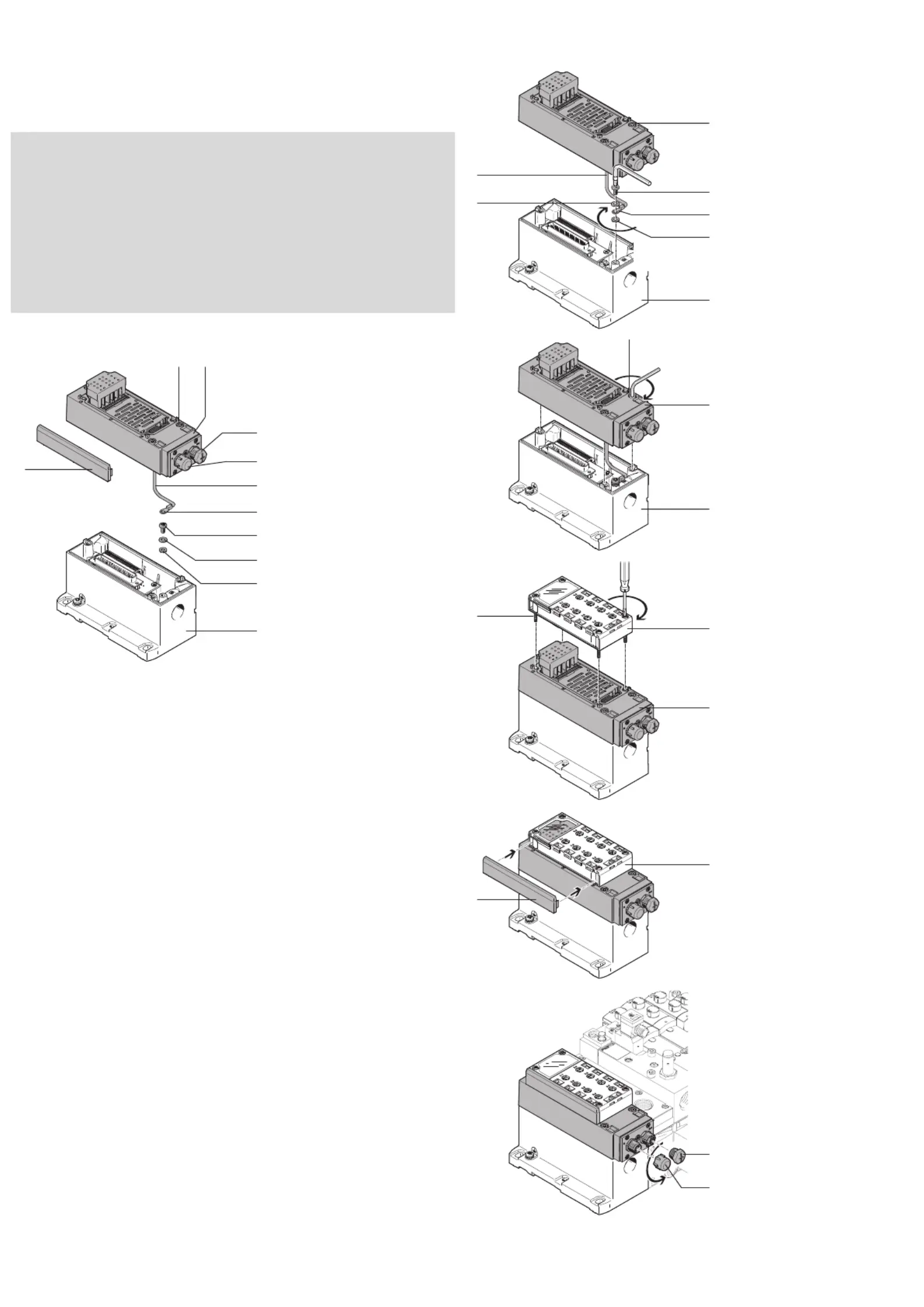
1.Teileliste
12803d_1
1AS-I-Modul
VAEM-S6-S-FAS-…
2Schutzkappe
Anschluss Out
3Schutzkappe
Anschluss In
4Erdungskabel
5Ringkabelschuh
6Schraube
(selbst schneidend)
M4x8 (Torx T20)
7Scheibe
B 4,3 DIN125
8Sicherungsscheibe
M4
9Blende
MPA-ASI-CPI
aJSchraube (3x)
M4x38
Nicht im Lieferumfang:
aAMultipolknoten
VABE-S6…LT-C-…
aBAnschlussblock
CPX-AB-…
aCSchraube (4x)
(selbst schneidend)
Delta PT 30 x 32
Bestimmungsgemäß dient das AS-I-Modul 1 als Zubehörteil zur elektri-
schen Anschaltung für E/A-Bussysteme bei einer VTSA-Ventilinsel.
2.Montage
12803d_2
•Verbinden Sie das AS-I-
Modul 1 und den Multipol-
knoten aA zur Funktions-
erdung mit dem Erdungs-
kabel 4 wie folgt:
– Führen Sie die Schraube 6
durch die Scheibe 7, den
Kabelschuh 5 und die Si-
cherungsscheibe 8.
– Drehen Sie die Schraube 6
fest, mit einem TORX-
Schraubendreher T20. Hal-
ten Sie das zulässige An-
ziehdrehmoment ein.
12803d_3
•Platzieren Sie das AS-I-
Modul 1 auf dem Multipol-
knoten aA.
•Drehen Sie die Schrauben aJ
fest. Halten Sie das zulässige
Anziehdrehmoment ein.
12803d_4
•Platzieren Sie den An-
schlussblock aB auf dem
AS-I-Modul 1.
•Drehen Sie die Schrauben aC
fest. Halten Sie das zulässige
Anziehdrehmoment ein.
12803d_5
•Drücken Sie die Blende 9 in
den Anschlussblock aB.
12803d_6
Zum Anschließen:
•Drehen Sie die Schutz-
kappen 2 und 3 an den
Anschlüssen IN / OUT herun-
ter.
1,5 Nm _ 20%
1 Nm 10% _
aA
8
7
6
2
5
4
9
aJ
3
1
1
aA
7
4
1 Nm 10% _
8
5
6
aA
1
aJ
aB
1
aC
9
aB
3
2
Produktspezifikationen
| Marke: | Festo |
| Kategorie: | Nicht kategorisiert |
| Modell: | VAEM-S6-S-FAS-4-4E |
Brauchst du Hilfe?
Wenn Sie Hilfe mit Festo VAEM-S6-S-FAS-4-4E benötigen, stellen Sie unten eine Frage und andere Benutzer werden Ihnen antworten
Bedienungsanleitung Nicht kategorisiert Festo

1 August 2025
1 August 2025
1 August 2025
1 August 2025
1 August 2025
1 August 2025
1 August 2025
1 August 2025
1 August 2025
1 August 2025
Bedienungsanleitung Nicht kategorisiert
Neueste Bedienungsanleitung für -Kategorien-
3 April 2026
3 April 2026
3 April 2026
3 April 2026
3 April 2026
3 April 2026
3 April 2026
3 April 2026
3 April 2026
3 April 2026