First Alert SA520B Bedienungsanleitung
First Alert Alarmanlage SA520B
Lies die bedienungsanleitung für First Alert SA520B (12 Seiten) kostenlos online; sie gehört zur Kategorie Alarmanlage. Dieses Handbuch wurde von 11 Personen als hilfreich bewertet und erhielt im Schnitt 4.8 Sterne aus 5 Bewertungen. Hast du eine Frage zu First Alert SA520B oder möchtest du andere Nutzer dieses Produkts befragen? Stelle eine Frage
Seite 1/12
BASIC SAFETY INFORMATION
ELECTRICAL SHOCK HAZARD. Turn off the power to the area where the smoke alarm is installed before removing it from
the mounting bracket. Failure to turn off the power first may result in serious electrical shock, injury or death.
•
This unit will not alert hearing impaired residents. It is recommended that you install special units
which use devices like flashing strobe lights to alert hearing impaired residents.
•
Installation of this unit must conform to the electrical codes in your area; Articles 210 and 300.3 (B) of NFPA 70 (NEC), NFPA 72,
NFPA 101; SBC (SBCCI); UBC (ICBO); NBC (BOCA); OTFDC (CABO), and any other local or building codes that may apply. Wiring and
installation must be performed by a licensed electrician. Failure to follow these guidelines may result in injury or property damage.
•
This unit must be powered by a 24-hour, 120VAC pure sine wave 60Hz circuit. Be sure the circuit
cannot be turned off by a switch, dimmer, or ground fault circuit interrupter. Failure to connect
this unit to a 24-hour circuit may prevent it from providing constant protection.
•
This smoke alarm must have AC or battery power to operate. If the AC power fails, battery back-up will allow
the alarm to sound for at least 4 minutes. If AC power fails and the battery is weak, protection should last
for at least 7 days. If AC power fails and the battery is dead or missing, the alarm cannot operate.
•
Never disconnect the power from an AC powered unit to stop an unwanted alarm. Doing so will disable the unit and remove
your protection. In the case of a true unwanted alarm open a window or fan the smoke away from the unit. The alarm will reset
automatically when it returns to normal operation. Never remove the batteries from a battery operated unit to stop an unwanted alarm
(caused by cooking smoke, etc.). Instead open a window or fan the smoke away from the unit. The alarm will reset automatically.
•
Unit will not operate without battery power. The smoke alarm cannot work until you activate the battery power pack.
•
Connect this unit ONLY to other compatible units. See “How To Install This Smoke Alarm” for details. Do not connect it to any other
type of alarm or auxiliary device. Connecting anything else to this unit may damage it or prevent it from operating properly.
•
Do not install this unit over an electrical junction box. Air currents around junction boxes can prevent smoke from reaching the
sensing chamber and prevent the unit from alarming. Only AC powered units are intended for installation over junction boxes.
•
This smoke alarm has a battery drawer which resists closing unless a battery is installed.
This warns you the unit will not operate under DC power without a battery.
•
Do not stand too close to the unit when the alarm is sounding. It is loud to wake you in an
emergency. Exposure to the horn at close range may harm your hearing.
•
Do not paint over the unit. Paint may clog the openings to the sensing chambers and prevent the unit from operating properly.
BEFORE YOU INSTALL THIS SMOKE ALARM
Important! Read “Recommended Locations for Smoke Alarms” and “Locations to Avoid for Smoke Alarms” before beginning. This unit
monitors the air, and when smoke reaches its sensing chamber, it alarms. It can give you more time to escape before fire spreads. This
unit can ONLY give an early warning of developing fires if it is installed, maintained and located where smoke can reach it, and where all
residents can hear it, as described in this manual. This unit will not sense gas, heat, or flame. It cannot prevent or extinguish fires.
Understand The Different Type of Smoke Alarms: Battery powered or electrical? Different smoke
alarms provide different types of protection. See “About Smoke Alarms” for details.
Know Where To Install Your Smoke Alarms: Fire Safety Professionals recommend at least one smoke alarm
on every level of your home, in every bedroom, and in every bedroom hallway or separate sleeping area. See
“Recommended Locations for Smoke Alarms” and “Locations to Avoid for Smoke Alarms” for details.
Know What Smoke Alarms Can and Can’t Do: A smoke alarm can help alert you to fire, giving you precious time to escape.
It can only sound an alarm once smoke reaches the sensor. See “Limitations of Smoke Alarms” for details.
Check Your Local Building Codes: This smoke alarm is designed to be used in a typical single-family home. It alone will not meet
requirements for boarding houses, apartment buildings, hotels or motels. See “Special Compliance Considerations” for details.
FOLLOW THESE INSTALLATION STEPS
The basic installation of this smoke alarm is similar whether you want to install one smoke alarm, or interconnect more than one smoke alarm. If you are
interconnecting more than one smoke alarm, you MUST read “Special Requirements For Interconnected Smoke Alarms” below before you begin installation
ELECTRICAL SHOCK HAZARD. Turn off power to the
area where you will install this unit at the circuit
breaker or fuse box before beginning installation.
Failure to turn off the power before installation may
result in serious electrical shock, injury or death.
1. Remove the mounting bracket from the base,
and attach it to the junction box.
2. Using wire nuts, connect the power
connector to the household wiring.
STAND-ALONE ALARM ONLY:
•
Connect the white wire on the power connector to the neutral wire in the junction box.
•
Connect the black wire on the power connector to the hot wire in the junction box.
•
Tuck the orange wire inside the junction box. It is used for interconnect only.
INTERCONNECTED UNITS ONLY:
Strip off about 1/2” (12 mm) of the plastic coating on the orange wire on the power connector.
•
Connect the white wire on the power connector to the neutral wire in the junction box.
•
Connect the black wire on the power connector to the hot wire in the junction box.
•
Connect the orange wire on the power connector to the interconnect wire in the junction box.
Repeat for each unit you are interconnecting. Never connect the hot or neutral wires in the junction
box to the orange interconnect wire. Never cross hot and neutral wires between alarms.
3. Plug the power connector into the back of the smoke alarm.
4. Position the base of the smoke alarm over the mounting bracket and turn. The alarm can be positioned over
the bracket every 90°. Turn the smoke alarm clockwise (right) until the unit is in place.
5. Check all connections.
Improper wiring of the power connector or the wiring leading to the power connector will cause damage to the alarm and may lead to a non-functioning alarm.
STAND-ALONE ALARM ONLY:
•
If you are only installing one alarm, restore power to the junction box.
INTERCONNECTED ALARMS ONLY:
•
If you are interconnecting multiple alarms, repeat steps 1-5 for each alarm
in the series. When you are finished, restore power to the junction box.
ELECTRICAL SHOCK HAZARD. Do not restore power until all alarms are completely installed. Restoring
power before installation is complete may result in serious electrical shock, injury or death.
6. Make sure the alarm is receiving AC power. Under normal operation, the Green power indicator light will shine continuously.
7. If the Green power indicator light does not light, TURN OFF POWER TO THE JUNCTION BOX and recheck all connections. If all connections
are correct and the Green power indicator still does not light when you restore the power, the unit should be replaced immediately.
FOLLOW THESE INSTALLATION STEPS (CONTINUED)...
8. Test each alarm. Press and hold the Test/Silence button until the unit alarms. When testing a series of interconnected
units you must test each unit individually. Make sure all units alarm when each one is tested.
If any unit in the series does not alarm, TURN OFF POWER and recheck connections. If it does not alarm when you restore power, replace it immediately.
Special Requirements For Interconnected Smoke Alarms
•
Failure to meet any of the above requirements could damage the units and cause them to malfunction, removing your protection.
•
AC and AC/DC smoke alarms can be interconnected. Under AC power, all units will alarm when one senses smoke. When power is
interrupted, only the AC/DC units in the series will continue to send and receive signals. AC powered smoke alarms will not operate.
Interconnected units can provide earlier warning of fire than stand-alone units, especially if a fire starts in a remote area of the dwelling.
If any unit in the series senses smoke, all units will alarm. To determine which smoke alarm initiated an alarm, see table:
On Initiating Alarms Red LED flashes rapidly
On All Other Alarms Red LED is Off
Interconnect units within a single family residence only. Otherwise all households will experience unwanted alarms when you
test any unit in the series. Interconnected units will only work if they are wired to compatible units and all requirements are met.
This unit is designed to be compatible with: First Alert
®
Smoke Alarm Models SA4120, SA4121B, SA100B, 9120 series and BRK
Electronics
®
Smoke Alarm Models 100S, 4120 series, 9120 series, 7010 series; BRK Electronics
®
Heat Alarm Models HD6135F,
HD6135FB; Smoke/CO Alarm Models SC6120B, SC9120B; CO Alarm Model CO5120B; Relay Modules RM3 and RM4.
INTERCONNECTED UNITS MUST MEET ALL OF THE FOLLOWING REQUIREMENTS:
•
A maximum of 18 compatible units may be interconnected (Maximum of 12 smoke alarms).
•
The same fuse or circuit breaker must power all interconnected units.
•
The total length of wire interconnecting the units should be less than 1000 feet (300 meters). This
type of wire is commonly available at Hardware and Electrical Supply stores.
•
All wiring must conform to all local electrical codes and NFPA 70 (NEC). Refer to NFPA 72, NFPA
101, and/or your local building code for further connection requirements.
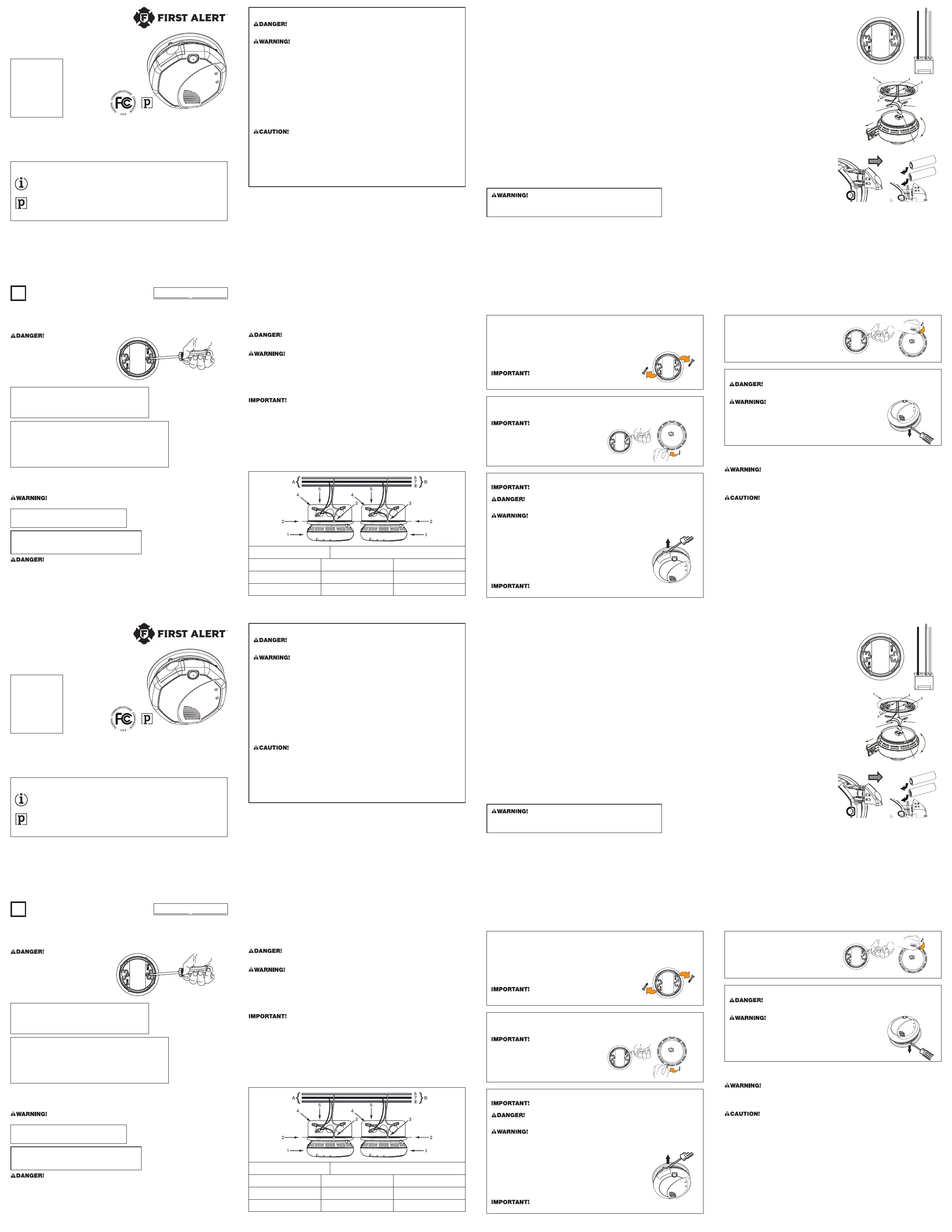
A. Unswitched 120VAC 60 Hz sourceB. To additional units; Maximum = 18 total (Maximum 12 smoke alarms)
1. Smoke Alarm2. Ceiling or Wall3. Power Connector
4. Wire Nut5. Junction Box6. Neutral Wire (Wht)
7. Interconnect Wire (Orange)8. Hot Wire (Blk)
OPTIONAL LOCKING FEATURE
The locking features are designed to discourage unauthorized removal of the battery or alarm. It is not necessary to
activate the locks in single-family households where unauthorized battery or alarm removal is not a concern.
These smoke alarms have two separate locking features: one to lock the battery compartment, and the other to lock the
smoke alarm to the mounting bracket. You can choose to use either feature independently, or use them both.
Tools you will need:
•
Needle-nose pliers or utility knife, standard flathead screwdriver.
Both locking features use locking pins, which are molded into the mounting bracket.
Using needle-nose pliers or a utility knife, remove one or both pins from the
mounting bracket, depending on how many locking features you want to use.
To permanently remove either lock, insert a flathead screwdriver between
the locking pin and the lock, and pry the pin out of the lock.
TO LOCK THE BATTERY COMPARTMENT
Do not lock the battery compartment until you have installed the battery and tested the battery back-up.
1. Push and hold Test/Silence button until the alarm sounds: 3 beeps, pause, 3 beeps, pause.
If the unit does not alarm during testing, DO NOT lock the
battery compartment! Install a new battery and test again. If
the smoke alarm still does not alarm, replace it immediately.
2. Using needle-nose pliers, detach one locking
pin from the mounting bracket.
3. Push the locking pin through the hole near the
battery drawer on the back of the smoke alarm.
TO UNLOCK THE BATTERY COMPARTMENT
Once the smoke alarm is installed, you must disconnect it from the AC power before unlocking the battery compartment.
ELECTRICAL SHOCK HAZARD. Turn off the power to the area where the smoke alarm is installed before removing it from
the mounting bracket. Failure to turn off the power first may result in serious electrical shock, injury or death.
Always discharge the branch circuit before servicing an AC or AC/DC smoke alarm. First, turn off the AC
power at the circuit breaker or fuse box. Next, remove the battery from smoke alarms with battery back-
up. Finally, press and hold the Test/Silence button for 5-10 seconds to discharge the branch circuit.
1. Remove the smoke alarm from the mounting bracket. If the unit is locked to
the bracket, see the section “To Unlock the Mounting Bracket.”
2. Disconnect the power connector by gently prying it away from the back of the smoke alarm.
3. Insert a flathead screwdriver under the head of the locking pin, and gently pry it out of the battery
compartment lock. (If you plan to relock the battery compartment, save the locking pin.)
4. To relock the battery compartment, close the battery door and reinsert locking pin in lock.
5. Reconnect the power connector to the back of the smoke alarm, reattach
the smoke alarm to the mounting bracket, and restore the power.
When replacing the battery, always test the smoke alarm before relocking the battery compartment.
TO LOCK THE MOUNTING BRACKET
1. Using needle-nose pliers, detach one
locking pin from mounting bracket.
2. Insert the locking pin into the lock located opposite
from the battery drawer as shown in the diagram.
3. When you attach the smoke alarm to the mounting bracket,
the locking pin’s head will fit into a notch on the bracket.
TO UNLOCK THE MOUNTING BRACKET
ELECTRICAL SHOCK HAZARD. Turn off the power to the area where the smoke alarm is installed before removing it from
the mounting bracket. Failure to turn off the power first may result in serious electrical shock, injury or death.
Always discharge the branch circuit before servicing an AC or AC/DC smoke
alarm. First, turn off the AC power at the circuit breaker or fuse box. Next, remove
the battery from smoke alarms with battery back-up. Finally, press and hold the
Test/Silence button for 5-10 seconds to discharge the branch circuit.
1. Insert a flathead screwdriver between the mounting bracket pin and the mounting bracket.
2. Pry the smoke alarm away from the bracket by turning both the screwdriver
and the smoke alarm counterclockwise (left) at the same time.
TESTING AND MAINTENANCE
WEEKLY TESTING
•
NEVER use an open flame of any kind to test this unit. You might accidentally damage or set fire to the unit or to your home.
The built-in test switch accurately tests the unit’s operation as required by Underwriters Laboratories, Inc. (UL).
•
If the alarm ever fails to test properly, replace it immediately. Products under warranty may be returned
to the manufacturer for replacement. See “Limited Warranty” at the end of this manual.
DO NOT stand close to the alarm when the horn is sounding. Exposure at close range may be
harmful to your hearing. When testing, step away when horn starts sounding.
It is important to test this unit every week to make sure it is working properly. Using the test button is the recommended way to
test this smoke alarm. Press and hold the test button on the cover of the unit until the alarm sounds (the unit may continue to alarm for
a few seconds after you release the button). If it does not alarm, make sure the unit is receiving power and test it again. If it still does not
alarm, replace it immediately. During testing, you will hear a loud, repeating horn pattern: 3 beeps, pause, 3 beeps, pause.
When testing a series of interconnected units you must test each unit individually. Make sure all units alarm when each one is tested.
REGULAR MAINTENANCE
This unit has been designed to be as maintenance-free as possible, but there are a few simple things you must do to keep it working properly:
•
Test it at least once a week.
•
Clean the smoke alarm at least once a month; gently vacuum the outside of the smoke alarm using your household vacuum’s
soft brush attachment. Test the smoke alarm. Never use water, cleaners or solvents since they may damage the unit.
•
If the smoke alarm becomes contaminated by excessive dirt, dust and/or grime, and cannot
be cleaned to avoid unwanted alarms, replace the unit immediately.
•
Relocate the unit if it sounds frequent unwanted alarms. See “Locations To Avoid For Smoke Alarms” for details.
•
When the battery back-up becomes weak, the smoke alarm will “chirp” about once a minute (the Low Battery Warning).
This warning should last 7 days, but you should replace the batteries immediately to continue your protection.
LOCATIONS TO AVOID FOR SMOKE ALARMS
FOR BEST PERFORMANCE, IT IS RECOMMENDED YOU AVOID INSTALLING SMOKE ALARMS IN THESE AREAS:
•
Where combustion particles are produced. Combustion particles form when something burns. Areas to avoid include poorly ventilated
kitchens, garages, and furnace rooms. Keep units at least 20 feet (6 meters) from the sources of combustion particles (stove, furnace, water
heater, space heater) if possible. In areas where a 20-foot (6-meter) distance is not possible – in modular, mobile, or smaller homes, for
example – it is recommended the smoke alarm be placed as far from these fuel-burning sources as possible. The placement recommendations
are intended to keep these alarms at a reasonable distance from a fuel-burning source, and thus reduce “unwanted” alarms. Unwanted
alarms can occur if a smoke alarm is placed directly next to a fuel-burning source. Ventilate these areas as much as possible.
•
In air streams near kitchens. Air currents can draw cooking smoke into the sensing chamber of a smoke alarm near the kitchen.
•
In very damp, humid or steamy areas, or directly near bathrooms with showers. Keep units at
least 10 feet (3 meters) away from showers, saunas, dishwashers, etc.
•
Where the temperatures are regularly below 40˚ F (4.4˚ C) or above 100˚ F (37.8˚ C), including
unheated buildings, outdoor rooms, porches, or unfinished attics or basements.
•
In very dusty, dirty, or greasy areas. Do not install a smoke alarm directly over the stove or range. Keep laundry room smoke alarms free of dust or lint.
•
Near fresh air vents, ceiling fans, or in very drafty areas. Drafts can blow smoke away from the unit, preventing it from reaching the sensing chamber.
•
In insect infested areas. Insects can clog openings to the sensing chamber and cause unwanted alarms.
•
Less than 12 inches (305mm) away from fluorescent lights. Electrical “noise” can interfere with the sensor.
•
In “dead air” spaces. “Dead air” spaces may prevent smoke from reaching the smoke alarm.
AVOIDING DEAD AIR SPACES
“Dead air” spaces may prevent smoke from reaching the smoke alarm. To avoid dead air spaces, follow the installation recommendations below.
On ceilings, install smoke alarms as close to the center of the ceiling as possible. If this is not possible,
install the smoke alarm at least 4 inches (102 mm) from the wall or corner.
For wall mounting (if allowed by building codes), the top edge of smoke alarms should be placed between 4
and 12 inches (102 and 305 mm) from the wall/ceiling line, below typical “dead air” spaces.
On a peaked, gabled, or cathedral ceiling, install the first smoke alarm within 3 feet (0.9 meters) of the peak of
the ceiling, measured horizontally. Additional smoke alarms may be required depending on the length, angle, etc.
of the ceiling’s slope. Refer to NFPA 72 for details on requirements for sloped or peaked ceilings.
HOW TO INSTALL THIS SMOKE ALARM
This smoke alarm is designed to be mounted on any standard wiring junction box up to a 4-inch (10 cm) size, on either the ceiling or wall (if allowed
by local codes). Read “Recommended Locations For Smoke Alarms” and “Locations to Avoid For Smoke Alarms” before you begin installation.
Tools you will need: Needle-nose pliers, standard flathead screwdriver, Phillips screwdriver.
Make sure the alarm is not receiving excessively noisy power. Examples of noisy power could be major
appliances on the same circuit, power from a generator or solar power, light dimmer on the same circuit
or mounted near fluorescent lighting. Excessively noisy power may cause damage to your alarm.
THE PARTS OF THIS SMOKE ALARM
The Mounting Bracket: To remove the mounting bracket from the alarm base, hold
the alarm base firmly and twist the mounting bracket counterclockwise. The mounting
bracket installs onto the junction box. It has a variety of screw slots to fit most boxes.
The Power Connector: The power connector plugs into a power
input block on the alarm. It supplies the unit with AC power.
The black wire is “hot.”
The white wire is neutral.
The orange wire is used for interconnect.
If you need to remove the power connector, turn POWER OFF first. Insert a
flat screwdriver blade between the power connector and the security tab inside
the power input block. Gently pry back the tab and pull the connector free.
THE PARTS OF THIS UNIT
1. Mounting Bracket
2. Mounting Slots
3. Locking Pins (break out of bracket)
4. Hot (Black) AC Wire
5. Neutral (White) AC Wire
6. Interconnect (Orange) Wire
7. Quick-Connect Power Connector
8. Turn this way to remove from bracket
9. Turn this way to attach to bracket
10. Slide-Out Battery Drawer
4
5
6
8
9
10
7
QUICK INSTALLATION INSTRUCTIONS
Easily expand an existing interconnected 120V AC hardwired
system by simply replacing one alarm in the series with the First
Alert
®
Model SA520. Then add additional battery-operated alarms
to expand the system with no additional electrical work.
1. Insert the batteries into the battery drawer of
the first alarm and close the drawer.
2. The alarm will sound with a chirp.
3. If you purchased the Talking Smoke and Carbon Monoxide
Alarm, you will now be prompted to set the alarm’s
location. Follow the direction given by the alarm.
NOTE: Steps 4 through 6 need to be completed within two minutes. If more than two minutes pass, the Green power
LED will stop blinking. Simply open the battery drawer of the second alarm and repeat steps 4 through 6.
4. Insert the batteries into the battery drawer of the next alarm. DO NOT CLOSE THE DRAWER.
5. Press and hold the test button and then close the battery drawer.
6. Once you hear the unit chirp, release the test button. The Green power LED will start to blink indicating the WIRELESS
INTERCONNECT alarm is waiting for program data from one of the other setup WIRELESS INTERCONNECT alarms.
7. Press and hold the test button on the first alarm, until the second alarm chirps and its Green power LED stops blinking. Then release the test button.
8. If you purchased the Talking Smoke and Carbon Monoxide Alarm, you will now be prompted
to set the alarm’s location. Follow the directions given by the alarm.
9. If you have purchased the hardwired battery back-up WIRELESS INTERCONNECT alarm, you can now connect
the hardwired alarm by installing the three-wire connector on the ceiling to the alarm.
10. Repeat steps 4-9 for additional WIRELESS INTERCONNECT alarms.
You have now successfully linked your new WIRELESS INTERCONNECT alarms. To add additional alarms at a later time, follow steps 4 through 9.
IMPORTANT! PLEASE READ
CAREFULLY AND SAVE.
The warnings/limitations card
and manual contains important
information about your smoke
alarm’s operation. If you are
installing this alarm for use
by others, you must leave this
manual—or a copy of it—with
the end user. Reference product
card for additional information.
USER’S MANUAL
WIRELESS INTERCONNECTED
HARDWIRED SMOKE ALARM
WITH BATTERY BACK-UP
INPUT: 120V AC ~, 60HZ, 0.09A
BATTERY BACK-UP
Printed in Mexico
M08-0149-160325-US_RevB L 01/18
Model SA520
CONFORMS TO UL STD 217
INTRODUCTION
Thank you for choosing First Alert
®
for your smoke alarm needs. You have purchased a state of the art smoke alarm designed to provide you with
early warning of a fire. Please take the time to read this manual and make the smoke alarm an integral part of your family’s safety plan.
All First Alert
®
smoke alarms conform to regulatory requirements, including UL217 and are designed to detect
particles of combustion. Smoke particles of varying number and size are produced in all fires.
Ionization technology is generally more sensitive than photoelectric technology at detecting small particles, which
tend to be produced in greater amounts by flaming fires, which consume combustible materials rapidly and spread
quickly. Sources of these fires may include paper burning in a wastebasket, or a grease fire in the kitchen.
Photoelectric technology is generally more sensitive than ionization technology at detecting large particles,
which tend to be produced in greater amounts by smoldering fires, which may smolder for hours before
bursting into flame. Sources of these fires may include cigarettes burning in couches or bedding.
For maximum protection, use both types of smoke alarms on each level and in every bedroom of your home.
© 2018 BRK Brands, Inc. All rights reserved. Distributed by BRK Brands, Inc.
•
BRK Brands, Inc.
is a subsidiary of Newell Brands Inc. (NYSE:NWL)
•
3901 Liberty Street, Aurora, IL 60504-8122
•
Customer Service Team: (800) 323-9005
•
www.firstalert.com
•
www.brkelectronics.com
Installed onReplace by
L
BASIC SAFETY INFORMATION
ELECTRICAL SHOCK HAZARD. Turn off the power to the area where the smoke alarm is installed before removing it from
the mounting bracket. Failure to turn off the power first may result in serious electrical shock, injury or death.
•
This unit will not alert hearing impaired residents. It is recommended that you install special units
which use devices like flashing strobe lights to alert hearing impaired residents.
•
Installation of this unit must conform to the electrical codes in your area; Articles 210 and 300.3 (B) of NFPA 70 (NEC), NFPA 72,
NFPA 101; SBC (SBCCI); UBC (ICBO); NBC (BOCA); OTFDC (CABO), and any other local or building codes that may apply. Wiring and
installation must be performed by a licensed electrician. Failure to follow these guidelines may result in injury or property damage.
•
This unit must be powered by a 24-hour, 120VAC pure sine wave 60Hz circuit. Be sure the circuit
cannot be turned off by a switch, dimmer, or ground fault circuit interrupter. Failure to connect
this unit to a 24-hour circuit may prevent it from providing constant protection.
•
This smoke alarm must have AC or battery power to operate. If the AC power fails, battery back-up will allow
the alarm to sound for at least 4 minutes. If AC power fails and the battery is weak, protection should last
for at least 7 days. If AC power fails and the battery is dead or missing, the alarm cannot operate.
•
Never disconnect the power from an AC powered unit to stop an unwanted alarm. Doing so will disable the unit and remove
your protection. In the case of a true unwanted alarm open a window or fan the smoke away from the unit. The alarm will reset
automatically when it returns to normal operation. Never remove the batteries from a battery operated unit to stop an unwanted alarm
(caused by cooking smoke, etc.). Instead open a window or fan the smoke away from the unit. The alarm will reset automatically.
•
Unit will not operate without battery power. The smoke alarm cannot work until you activate the battery power pack.
•
Connect this unit ONLY to other compatible units. See “How To Install This Smoke Alarm” for details. Do not connect it to any other
type of alarm or auxiliary device. Connecting anything else to this unit may damage it or prevent it from operating properly.
•
Do not install this unit over an electrical junction box. Air currents around junction boxes can prevent smoke from reaching the
sensing chamber and prevent the unit from alarming. Only AC powered units are intended for installation over junction boxes.
•
This smoke alarm has a battery drawer which resists closing unless a battery is installed.
This warns you the unit will not operate under DC power without a battery.
•
Do not stand too close to the unit when the alarm is sounding. It is loud to wake you in an
emergency. Exposure to the horn at close range may harm your hearing.
•
Do not paint over the unit. Paint may clog the openings to the sensing chambers and prevent the unit from operating properly.
BEFORE YOU INSTALL THIS SMOKE ALARM
Important! Read “Recommended Locations for Smoke Alarms” and “Locations to Avoid for Smoke Alarms” before beginning. This unit
monitors the air, and when smoke reaches its sensing chamber, it alarms. It can give you more time to escape before fire spreads. This
unit can ONLY give an early warning of developing fires if it is installed, maintained and located where smoke can reach it, and where all
residents can hear it, as described in this manual. This unit will not sense gas, heat, or flame. It cannot prevent or extinguish fires.
Understand The Different Type of Smoke Alarms: Battery powered or electrical? Different smoke
alarms provide different types of protection. See “About Smoke Alarms” for details.
Know Where To Install Your Smoke Alarms: Fire Safety Professionals recommend at least one smoke alarm
on every level of your home, in every bedroom, and in every bedroom hallway or separate sleeping area. See
“Recommended Locations for Smoke Alarms” and “Locations to Avoid for Smoke Alarms” for details.
Know What Smoke Alarms Can and Can’t Do: A smoke alarm can help alert you to fire, giving you precious time to escape.
It can only sound an alarm once smoke reaches the sensor. See “Limitations of Smoke Alarms” for details.
Check Your Local Building Codes: This smoke alarm is designed to be used in a typical single-family home. It alone will not meet
requirements for boarding houses, apartment buildings, hotels or motels. See “Special Compliance Considerations” for details.
FOLLOW THESE INSTALLATION STEPS
The basic installation of this smoke alarm is similar whether you want to install one smoke alarm, or interconnect more than one smoke alarm. If you are
interconnecting more than one smoke alarm, you MUST read “Special Requirements For Interconnected Smoke Alarms” below before you begin installation
ELECTRICAL SHOCK HAZARD. Turn off power to the
area where you will install this unit at the circuit
breaker or fuse box before beginning installation.
Failure to turn off the power before installation may
result in serious electrical shock, injury or death.
1. Remove the mounting bracket from the base,
and attach it to the junction box.
2. Using wire nuts, connect the power
connector to the household wiring.
STAND-ALONE ALARM ONLY:
•
Connect the white wire on the power connector to the neutral wire in the junction box.
•
Connect the black wire on the power connector to the hot wire in the junction box.
•
Tuck the orange wire inside the junction box. It is used for interconnect only.
INTERCONNECTED UNITS ONLY:
Strip off about 1/2” (12 mm) of the plastic coating on the orange wire on the power connector.
•
Connect the white wire on the power connector to the neutral wire in the junction box.
•
Connect the black wire on the power connector to the hot wire in the junction box.
•
Connect the orange wire on the power connector to the interconnect wire in the junction box.
Repeat for each unit you are interconnecting. Never connect the hot or neutral wires in the junction
box to the orange interconnect wire. Never cross hot and neutral wires between alarms.
3. Plug the power connector into the back of the smoke alarm.
4. Position the base of the smoke alarm over the mounting bracket and turn. The alarm can be positioned over
the bracket every 90°. Turn the smoke alarm clockwise (right) until the unit is in place.
5. Check all connections.
Improper wiring of the power connector or the wiring leading to the power connector will cause damage to the alarm and may lead to a non-functioning alarm.
STAND-ALONE ALARM ONLY:
•
If you are only installing one alarm, restore power to the junction box.
INTERCONNECTED ALARMS ONLY:
•
If you are interconnecting multiple alarms, repeat steps 1-5 for each alarm
in the series. When you are finished, restore power to the junction box.
ELECTRICAL SHOCK HAZARD. Do not restore power until all alarms are completely installed. Restoring
power before installation is complete may result in serious electrical shock, injury or death.
6. Make sure the alarm is receiving AC power. Under normal operation, the Green power indicator light will shine continuously.
7. If the Green power indicator light does not light, TURN OFF POWER TO THE JUNCTION BOX and recheck all connections. If all connections
are correct and the Green power indicator still does not light when you restore the power, the unit should be replaced immediately.
FOLLOW THESE INSTALLATION STEPS (CONTINUED)...
8. Test each alarm. Press and hold the Test/Silence button until the unit alarms. When testing a series of interconnected
units you must test each unit individually. Make sure all units alarm when each one is tested.
If any unit in the series does not alarm, TURN OFF POWER and recheck connections. If it does not alarm when you restore power, replace it immediately.
Special Requirements For Interconnected Smoke Alarms
•
Failure to meet any of the above requirements could damage the units and cause them to malfunction, removing your protection.
•
AC and AC/DC smoke alarms can be interconnected. Under AC power, all units will alarm when one senses smoke. When power is
interrupted, only the AC/DC units in the series will continue to send and receive signals. AC powered smoke alarms will not operate.
Interconnected units can provide earlier warning of fire than stand-alone units, especially if a fire starts in a remote area of the dwelling.
If any unit in the series senses smoke, all units will alarm. To determine which smoke alarm initiated an alarm, see table:
On Initiating Alarms Red LED flashes rapidly
On All Other Alarms Red LED is Off
Interconnect units within a single family residence only. Otherwise all households will experience unwanted alarms when you
test any unit in the series. Interconnected units will only work if they are wired to compatible units and all requirements are met.
This unit is designed to be compatible with: First Alert
®
Smoke Alarm Models SA4120, SA4121B, SA100B, 9120 series and BRK
Electronics
®
Smoke Alarm Models 100S, 4120 series, 9120 series, 7010 series; BRK Electronics
®
Heat Alarm Models HD6135F,
HD6135FB; Smoke/CO Alarm Models SC6120B, SC9120B; CO Alarm Model CO5120B; Relay Modules RM3 and RM4.
INTERCONNECTED UNITS MUST MEET ALL OF THE FOLLOWING REQUIREMENTS:
•
A maximum of 18 compatible units may be interconnected (Maximum of 12 smoke alarms).
•
The same fuse or circuit breaker must power all interconnected units.
•
The total length of wire interconnecting the units should be less than 1000 feet (300 meters). This
type of wire is commonly available at Hardware and Electrical Supply stores.
•
All wiring must conform to all local electrical codes and NFPA 70 (NEC). Refer to NFPA 72, NFPA
101, and/or your local building code for further connection requirements.
A. Unswitched 120VAC 60 Hz sourceB. To additional units; Maximum = 18 total (Maximum 12 smoke alarms)
1. Smoke Alarm2. Ceiling or Wall3. Power Connector
4. Wire Nut5. Junction Box6. Neutral Wire (Wht)
7. Interconnect Wire (Orange)8. Hot Wire (Blk)
OPTIONAL LOCKING FEATURE
The locking features are designed to discourage unauthorized removal of the battery or alarm. It is not necessary to
activate the locks in single-family households where unauthorized battery or alarm removal is not a concern.
These smoke alarms have two separate locking features: one to lock the battery compartment, and the other to lock the
smoke alarm to the mounting bracket. You can choose to use either feature independently, or use them both.
Tools you will need:
•
Needle-nose pliers or utility knife, standard flathead screwdriver.
Both locking features use locking pins, which are molded into the mounting bracket.
Using needle-nose pliers or a utility knife, remove one or both pins from the
mounting bracket, depending on how many locking features you want to use.
To permanently remove either lock, insert a flathead screwdriver between
the locking pin and the lock, and pry the pin out of the lock.
TO LOCK THE BATTERY COMPARTMENT
Do not lock the battery compartment until you have installed the battery and tested the battery back-up.
1. Push and hold Test/Silence button until the alarm sounds: 3 beeps, pause, 3 beeps, pause.
If the unit does not alarm during testing, DO NOT lock the
battery compartment! Install a new battery and test again. If
the smoke alarm still does not alarm, replace it immediately.
2. Using needle-nose pliers, detach one locking
pin from the mounting bracket.
3. Push the locking pin through the hole near the
battery drawer on the back of the smoke alarm.
TO UNLOCK THE BATTERY COMPARTMENT
Once the smoke alarm is installed, you must disconnect it from the AC power before unlocking the battery compartment.
ELECTRICAL SHOCK HAZARD. Turn off the power to the area where the smoke alarm is installed before removing it from
the mounting bracket. Failure to turn off the power first may result in serious electrical shock, injury or death.
Always discharge the branch circuit before servicing an AC or AC/DC smoke alarm. First, turn off the AC
power at the circuit breaker or fuse box. Next, remove the battery from smoke alarms with battery back-
up. Finally, press and hold the Test/Silence button for 5-10 seconds to discharge the branch circuit.
1. Remove the smoke alarm from the mounting bracket. If the unit is locked to
the bracket, see the section “To Unlock the Mounting Bracket.”
2. Disconnect the power connector by gently prying it away from the back of the smoke alarm.
3. Insert a flathead screwdriver under the head of the locking pin, and gently pry it out of the battery
compartment lock. (If you plan to relock the battery compartment, save the locking pin.)
4. To relock the battery compartment, close the battery door and reinsert locking pin in lock.
5. Reconnect the power connector to the back of the smoke alarm, reattach
the smoke alarm to the mounting bracket, and restore the power.
When replacing the battery, always test the smoke alarm before relocking the battery compartment.
TO LOCK THE MOUNTING BRACKET
1. Using needle-nose pliers, detach one
locking pin from mounting bracket.
2. Insert the locking pin into the lock located opposite
from the battery drawer as shown in the diagram.
3. When you attach the smoke alarm to the mounting bracket,
the locking pin’s head will fit into a notch on the bracket.
TO UNLOCK THE MOUNTING BRACKET
ELECTRICAL SHOCK HAZARD. Turn off the power to the area where the smoke alarm is installed before removing it from
the mounting bracket. Failure to turn off the power first may result in serious electrical shock, injury or death.
Always discharge the branch circuit before servicing an AC or AC/DC smoke
alarm. First, turn off the AC power at the circuit breaker or fuse box. Next, remove
the battery from smoke alarms with battery back-up. Finally, press and hold the
Test/Silence button for 5-10 seconds to discharge the branch circuit.
1. Insert a flathead screwdriver between the mounting bracket pin and the mounting bracket.
2. Pry the smoke alarm away from the bracket by turning both the screwdriver
and the smoke alarm counterclockwise (left) at the same time.
TESTING AND MAINTENANCE
WEEKLY TESTING
•
NEVER use an open flame of any kind to test this unit. You might accidentally damage or set fire to the unit or to your home.
The built-in test switch accurately tests the unit’s operation as required by Underwriters Laboratories, Inc. (UL).
•
If the alarm ever fails to test properly, replace it immediately. Products under warranty may be returned
to the manufacturer for replacement. See “Limited Warranty” at the end of this manual.
DO NOT stand close to the alarm when the horn is sounding. Exposure at close range may be
harmful to your hearing. When testing, step away when horn starts sounding.
It is important to test this unit every week to make sure it is working properly. Using the test button is the recommended way to
test this smoke alarm. Press and hold the test button on the cover of the unit until the alarm sounds (the unit may continue to alarm for
a few seconds after you release the button). If it does not alarm, make sure the unit is receiving power and test it again. If it still does not
alarm, replace it immediately. During testing, you will hear a loud, repeating horn pattern: 3 beeps, pause, 3 beeps, pause.
When testing a series of interconnected units you must test each unit individually. Make sure all units alarm when each one is tested.
REGULAR MAINTENANCE
This unit has been designed to be as maintenance-free as possible, but there are a few simple things you must do to keep it working properly:
•
Test it at least once a week.
•
Clean the smoke alarm at least once a month; gently vacuum the outside of the smoke alarm using your household vacuum’s
soft brush attachment. Test the smoke alarm. Never use water, cleaners or solvents since they may damage the unit.
•
If the smoke alarm becomes contaminated by excessive dirt, dust and/or grime, and cannot
be cleaned to avoid unwanted alarms, replace the unit immediately.
•
Relocate the unit if it sounds frequent unwanted alarms. See “Locations To Avoid For Smoke Alarms” for details.
•
When the battery back-up becomes weak, the smoke alarm will “chirp” about once a minute (the Low Battery Warning).
This warning should last 7 days, but you should replace the batteries immediately to continue your protection.
LOCATIONS TO AVOID FOR SMOKE ALARMS
FOR BEST PERFORMANCE, IT IS RECOMMENDED YOU AVOID INSTALLING SMOKE ALARMS IN THESE AREAS:
•
Where combustion particles are produced. Combustion particles form when something burns. Areas to avoid include poorly ventilated
kitchens, garages, and furnace rooms. Keep units at least 20 feet (6 meters) from the sources of combustion particles (stove, furnace, water
heater, space heater) if possible. In areas where a 20-foot (6-meter) distance is not possible – in modular, mobile, or smaller homes, for
example – it is recommended the smoke alarm be placed as far from these fuel-burning sources as possible. The placement recommendations
are intended to keep these alarms at a reasonable distance from a fuel-burning source, and thus reduce “unwanted” alarms. Unwanted
alarms can occur if a smoke alarm is placed directly next to a fuel-burning source. Ventilate these areas as much as possible.
•
In air streams near kitchens. Air currents can draw cooking smoke into the sensing chamber of a smoke alarm near the kitchen.
•
In very damp, humid or steamy areas, or directly near bathrooms with showers. Keep units at
least 10 feet (3 meters) away from showers, saunas, dishwashers, etc.
•
Where the temperatures are regularly below 40˚ F (4.4˚ C) or above 100˚ F (37.8˚ C), including
unheated buildings, outdoor rooms, porches, or unfinished attics or basements.
•
In very dusty, dirty, or greasy areas. Do not install a smoke alarm directly over the stove or range. Keep laundry room smoke alarms free of dust or lint.
•
Near fresh air vents, ceiling fans, or in very drafty areas. Drafts can blow smoke away from the unit, preventing it from reaching the sensing chamber.
•
In insect infested areas. Insects can clog openings to the sensing chamber and cause unwanted alarms.
•
Less than 12 inches (305mm) away from fluorescent lights. Electrical “noise” can interfere with the sensor.
•
In “dead air” spaces. “Dead air” spaces may prevent smoke from reaching the smoke alarm.
AVOIDING DEAD AIR SPACES
“Dead air” spaces may prevent smoke from reaching the smoke alarm. To avoid dead air spaces, follow the installation recommendations below.
On ceilings, install smoke alarms as close to the center of the ceiling as possible. If this is not possible,
install the smoke alarm at least 4 inches (102 mm) from the wall or corner.
For wall mounting (if allowed by building codes), the top edge of smoke alarms should be placed between 4
and 12 inches (102 and 305 mm) from the wall/ceiling line, below typical “dead air” spaces.
On a peaked, gabled, or cathedral ceiling, install the first smoke alarm within 3 feet (0.9 meters) of the peak of
the ceiling, measured horizontally. Additional smoke alarms may be required depending on the length, angle, etc.
of the ceiling’s slope. Refer to NFPA 72 for details on requirements for sloped or peaked ceilings.
HOW TO INSTALL THIS SMOKE ALARM
This smoke alarm is designed to be mounted on any standard wiring junction box up to a 4-inch (10 cm) size, on either the ceiling or wall (if allowed
by local codes). Read “Recommended Locations For Smoke Alarms” and “Locations to Avoid For Smoke Alarms” before you begin installation.
Tools you will need: Needle-nose pliers, standard flathead screwdriver, Phillips screwdriver.
Make sure the alarm is not receiving excessively noisy power. Examples of noisy power could be major
appliances on the same circuit, power from a generator or solar power, light dimmer on the same circuit
or mounted near fluorescent lighting. Excessively noisy power may cause damage to your alarm.
THE PARTS OF THIS SMOKE ALARM
The Mounting Bracket: To remove the mounting bracket from the alarm base, hold
the alarm base firmly and twist the mounting bracket counterclockwise. The mounting
bracket installs onto the junction box. It has a variety of screw slots to fit most boxes.
The Power Connector: The power connector plugs into a power
input block on the alarm. It supplies the unit with AC power.
The black wire is “hot.”
The white wire is neutral.
The orange wire is used for interconnect.
If you need to remove the power connector, turn POWER OFF first. Insert a
flat screwdriver blade between the power connector and the security tab inside
the power input block. Gently pry back the tab and pull the connector free.
THE PARTS OF THIS UNIT
1. Mounting Bracket
2. Mounting Slots
3. Locking Pins (break out of bracket)
4. Hot (Black) AC Wire
5. Neutral (White) AC Wire
6. Interconnect (Orange) Wire
7. Quick-Connect Power Connector
8. Turn this way to remove from bracket
9. Turn this way to attach to bracket
10. Slide-Out Battery Drawer
4
5
6
8
9
10
7
QUICK INSTALLATION INSTRUCTIONS
Easily expand an existing interconnected 120V AC hardwired
system by simply replacing one alarm in the series with the First
Alert
®
Model SA520. Then add additional battery-operated alarms
to expand the system with no additional electrical work.
1. Insert the batteries into the battery drawer of
the first alarm and close the drawer.
2. The alarm will sound with a chirp.
3. If you purchased the Talking Smoke and Carbon Monoxide
Alarm, you will now be prompted to set the alarm’s
location. Follow the direction given by the alarm.
NOTE: Steps 4 through 6 need to be completed within two minutes. If more than two minutes pass, the Green power
LED will stop blinking. Simply open the battery drawer of the second alarm and repeat steps 4 through 6.
4. Insert the batteries into the battery drawer of the next alarm. DO NOT CLOSE THE DRAWER.
5. Press and hold the test button and then close the battery drawer.
6. Once you hear the unit chirp, release the test button. The Green power LED will start to blink indicating the WIRELESS
INTERCONNECT alarm is waiting for program data from one of the other setup WIRELESS INTERCONNECT alarms.
7. Press and hold the test button on the first alarm, until the second alarm chirps and its Green power LED stops blinking. Then release the test button.
8. If you purchased the Talking Smoke and Carbon Monoxide Alarm, you will now be prompted
to set the alarm’s location. Follow the directions given by the alarm.
9. If you have purchased the hardwired battery back-up WIRELESS INTERCONNECT alarm, you can now connect
the hardwired alarm by installing the three-wire connector on the ceiling to the alarm.
10. Repeat steps 4-9 for additional WIRELESS INTERCONNECT alarms.
You have now successfully linked your new WIRELESS INTERCONNECT alarms. To add additional alarms at a later time, follow steps 4 through 9.
IMPORTANT! PLEASE READ
CAREFULLY AND SAVE.
The warnings/limitations card
and manual contains important
information about your smoke
alarm’s operation. If you are
installing this alarm for use
by others, you must leave this
manual—or a copy of it—with
the end user. Reference product
card for additional information.
USER’S MANUAL
WIRELESS INTERCONNECTED
HARDWIRED SMOKE ALARM
WITH BATTERY BACK-UP
INPUT: 120V AC ~, 60HZ, 0.09A
BATTERY BACK-UP
Printed in Mexico
M08-0149-160325-US_RevB L 01/18
Model SA520
CONFORMS TO UL STD 217
INTRODUCTION
Thank you for choosing First Alert
®
for your smoke alarm needs. You have purchased a state of the art smoke alarm designed to provide you with
early warning of a fire. Please take the time to read this manual and make the smoke alarm an integral part of your family’s safety plan.
All First Alert
®
smoke alarms conform to regulatory requirements, including UL217 and are designed to detect
particles of combustion. Smoke particles of varying number and size are produced in all fires.
Ionization technology is generally more sensitive than photoelectric technology at detecting small particles, which
tend to be produced in greater amounts by flaming fires, which consume combustible materials rapidly and spread
quickly. Sources of these fires may include paper burning in a wastebasket, or a grease fire in the kitchen.
Photoelectric technology is generally more sensitive than ionization technology at detecting large particles,
which tend to be produced in greater amounts by smoldering fires, which may smolder for hours before
bursting into flame. Sources of these fires may include cigarettes burning in couches or bedding.
For maximum protection, use both types of smoke alarms on each level and in every bedroom of your home.
© 2018 BRK Brands, Inc. All rights reserved. Distributed by BRK Brands, Inc.
•
BRK Brands, Inc.
is a subsidiary of Newell Brands Inc. (NYSE:NWL)
•
3901 Liberty Street, Aurora, IL 60504-8122
•
Customer Service Team: (800) 323-9005
•
www.firstalert.com
•
www.brkelectronics.com
Installed onReplace by
L
Produktspezifikationen
| Marke: | First Alert |
| Kategorie: | Alarmanlage |
| Modell: | SA520B |
Brauchst du Hilfe?
Wenn Sie Hilfe mit First Alert SA520B benötigen, stellen Sie unten eine Frage und andere Benutzer werden Ihnen antworten
Bedienungsanleitung Alarmanlage First Alert

10 März 2026
Bedienungsanleitung Alarmanlage
Neueste Bedienungsanleitung für -Kategorien-
2 April 2026
2 April 2026
1 April 2026
21 März 2026
16 März 2026
11 März 2026
10 März 2026
16 Februar 2026
15 Februar 2026
14 Februar 2026