Hanwha Vision SBP-301HF Bedienungsanleitung
Hanwha Vision Nicht kategorisiert SBP-301HF
Lies die bedienungsanleitung für Hanwha Vision SBP-301HF (2 Seiten) kostenlos online; sie gehört zur Kategorie Nicht kategorisiert. Dieses Handbuch wurde von 5 Personen als hilfreich bewertet und erhielt im Schnitt 4.9 Sterne aus 3 Bewertungen. Hast du eine Frage zu Hanwha Vision SBP-301HF oder möchtest du andere Nutzer dieses Produkts befragen? Stelle eine Frage
Seite 1/2
PT01-004092A
mqMNJMMQMVO^
한국어
1.
Cap
을
화살표
방향으로
회전시켜
Cap
과
Joint
를
분리하세요
.
(Figure 1)
2.
Mount
또는
Pole
외부로
노출된
Cable
을
Joint
로
통과시키세요
. (Figure 2)
3.
Joint
를
화살표
방향으로
회전하여
두
부재를
체결하세요
.
(Figure 3)
단
, PELCO
社
제품과
같이
NPT TAP
용
Mount
에
체결하는
경우
,
액세서리로
제공된
Coupling
에
Teflon tape
를
감아
Coupling
을
체결한
후
Joint
부품을
체결하여
조립하세요
.
(Figure 4)
M
Mount
또는
Pole
을
통해서
외부의
습기가
다량으로
유입될
수
있는
장소에
본
제품을
설치할
경우
액세서리로
포함된
BUSH
를
사용하여
외부
습기의
유입을
차단하세요
. (Figure 5)
-
BUSH
에
그리스를
적당량
도포한
후
,
케이블을
BUSH
의
각
홀에
맞춰
체결하세요
.
케이블이
체결되지
않는
홀에는
PIN
을
사용하여
홀을
막으세요
. (Figure 6)
-
BUSH
를
그림처럼
하우징
내측
상단
Optical Cable
에
체결하세요
.
이때
, POWER CABLE
을
전체적으로
눌러주어
BUSH
가
단면도처럼
“
하우징
”
에
정확히
체결하도록
하세요
. (Figure 7)
4.
Optical Cable
에
SFP Module
을
체결하세요
. (Figure 8)
5.
본체의
SFP SLOT
에
체결하세요
. (Figure 9)
6.
본체
RIB
와
Joint
홈
형상의
방향을
맞추어서
두
부재를
결합
후
화살표
방향으로
Cap
을
회전시켜서
두
부재를
체결하세요
.
(Figure 10)
J
단
,
두
부재
체결
시
Optical Cable
이
내부에서
접히지
않도록
Optical Cable
을
외부에서
당겨주면서
두
부재를
결합하세요
.
(Figure 11)
7.
CAP
이
반대방향으로
풀리는
것을
방지하도록
CAP
의
양쪽에
있는
나사를
회전시키세요
.
(
나사는
완전히
내부로
들어가지
않고
일정
깊이만
들어갑니다
.)
(Figure 12)
8.
(SBP-300HF) Ethernet cable
을
I/F PCB
에
연결하세요
.
외부
전원
케이블과
본체의
전원
공급
케이블을
함께
전원용
터미널
블럭에
결합
후
그림과
같이
I/F PCB
에
연결하세요
.
(Figure 13)
9.
(SBP-301HF/302HF/303HF) 8
번의
연결과정과
동일합니다
.
I/F PCB
의
전원
및
커넥터
연결
배치는
그림을
참고하세요
.
(Figure 14)
10.
I/F PCB
를
본체에
체결한
후
카메라의
안전케이블을
본체에
연결하세요
. (Figure 15)
11.
인스톨
베이스와
카메라
본체의
방향
참고
표시가
들어맞도록
결합하세요
. (Figure 16)
12.
카메라를
화살표
방향으로
돌려서
위
,
아래의
참고
표시부가
오른쪽
이미지와
같이
되도록
회전시키세요
. (Figure 17)
13.
육각나사
3
개를
이용하여
본체와
카메라를
고정시키세요
.
(Figure 18)
•
Speed
설정방법
기본
설정은
1Gbps
이며
, Switch
“
ON
”
하면
100Mbps
로
설정
가능합니다
. (Figure 13)
•
"
네트워크
끊어짐
"
이벤트
미지원
본
제품은
네트워크
PTZ
카메라의
액세서리
제품으로
광케이블
탈착시
,
“
네트워크
끊어짐
”
알람
기능을
지원하지
않습니다
.
English
1. Turn the cap in the direction shown by the arrow to separate
the cap from the joint. (Figure 1)
2. Pass the exposed cable to the outside of the mount or pole
through the joint. (Figure 2)
3. Turn the joint in the direction shown by the arrow to connect
the two materials. (Figure 3)
If the joint part is fastened to an NPT TAP mount, such as
in the product from PELCO, wrap the Teflon tape to the
accessory coupling, fasten the coupling and then fasten the
joint part. (Figure 4)
M
If the product is installed in an area where outside moisture can
penetrate through the mount or pole, use the accessory bush to
block the inflow of outside moisture. (Figure 5)
-Coat the bush with grease and connect the cable to the correct
hole of the bush. Plug the remaining holes with the pins. (Figure 6)
-Connect the bush to the optical cable at the top, inside the
housing, as shown in the figure. Press the power cable
thro
ughout its length so that the bush is correctly fastened to the
housing as shown in the cross-sectional diagram. (Figure 7)
4. Connect the optical cable to the SFP module. (Figure 8)
Use UL Recognized, Class I Laser SFP module
5. Fasten the SFP module to the SFP slot in the main body.
(Figure 9)
6. Connect the main body rib and joint groove by matching
the shape and then fasten together by turning the cap in the
direction shown by the arrow. (Figure 10)
J
When fastening the two materials, pull the optical cable from the
outside so that it is not bent inside. (Figure 11)
7. Turn the screws on both sides of the cap to prevent the cap
from coming loose in the opposite direction.
(The screws are not completely inside, as only a specific
length is inserted.) (Figure 12)
8. (SBP-300HF) Connect the Ethernet cable to the I/F PCB.
Plug the external power cable and power supply cable of the
main body into the power terminal block an
d connect them to
the I/F PCB as shown in the figure. (Figure 13)
9. (SBP-301HF/302HF/303HF) Same as Step 8.
Refer to the figure for the layout of the I/F PCB power and
connector connection. (Figure 14)
10. Fasten the I/F PCB to the main body and connect the safety
cable of the camera to the main body. (Figure 15)
11. Connect the installed base and the camera main body by
matching the direction reference indicators. (Figure 16)
12. Turn the camera in the direction shown by the arrow so that
the reference indicators at the top and bottom are the same
as in the image to the right. (Figure 17)
13. Fasten the main body and camera using the 3 hexagonal
screws. (Figure 18)
14. This product is intended to be supplied by Power Unit
marked “Class 2” or “LPS” and rated 24 Vac(50 or 60 Hz),
min. 3.1 A. (Including Main unit)
•Setting Speed
The default setting is 1 Gbps; the speed can be set to 100 Mbps
if the s
witch is in the “ON” position. (Figure 13)
•Does not support “Network disconnection” event
This product does not support the “Network disconnection”
alarm function when connecting or disconnecting a fiber optic
cable as an accessory of Network PTZ Camera.
Français
1. Tournez le bouchon dans la direction indiquée par la flèche
afin de le séparer du raccord. (Schéma 1)
2. Passez le câble exposé vers l’extérieur de la fixation ou du
bras dans le raccord. (Schéma 2)
3. Tournez le raccord dans la direction indiquée par la flèche afin
de connecter les deux matériaux. (Schéma 3)
Si le raccord est attachéàune fixation avec filetage NPT,
comme dans le produit de PELCO, enveloppez la bande
T
eflon sur le couplage de l’accessoire, serrez le couplage puis
serrez le raccord. (Schéma 4)
M
Si le produit est installé dans une zone où de l'humidité extérieure
peut pénétrer dans la fixation ou le bras, utilisez la douille de
l'accessoire pour bloquer l'entrée de cette humidité. (Schéma 5)
-Enduisez la douille de graisse et connectez le câble au trou
approprié de la douille. Bouchez les autres trous avec les broches.
(Schéma 6)
-Connectez la douille au câble optique dans la partie supérieure,
à l'intérieur du boîtier, comme indiqué dans le schéma. Appuyez
sur le câble d'alimentation sur sa longueur pour que la douille
soit correctement fixée au boîtier comme indiqué dans le plan en
coupe. (Schéma 7)
4. Connectez le câble optique au module SFP. (Schéma 8)
5. Fixez le module SFP à la fente SFP dans le corps principal.
(Schéma 9)
6. Connectez la nervure du corps principal et la rainure du
raccord en faisa
nt correspondre la forme, puis serrez
ensemble en tournant le bouchon dans la direction indiquée
par la flèche. (Schéma 10)
J
Lors de la fixation des deux matériaux, tirez le câble optique de
l'extérieur pour qu'il ne soit pas plié à l'intérieur. (Schéma 11)
7. Tournez les vis sur les deux côtés du bouchon pour éviter qu’il
ne soit pas desserré dans la direction opposée.
(Les vis ne sont pas complètementà l’intérieur, car seule une
longueur spécifique est insér
ée.) (Schéma 12)
8. (SBP-300HF) Connectez le câble Ethernet à la carte de circuit
imprimé I/F.
Branchez le câble d’alimentation externe et le câble
d’alimentation du corps principal sur le bloc de jonction
d’alimentation et connectez-les à la carte de circuit imprimé I/F
comme indiqué dans le schéma. (Schéma 13)
9. (SBP-301HF/302HF/303HF) Identique à l’étape 8.
Voir le schéma pour la disposition de l’alimentation de la carte
de circu
it imprimé I/F et du branchement du connecteur.
(Schéma 14)
10. Serrez la carte de circuit imprimé I/F sur le corps principal
et connectez le câble de sécurité de la caméra sur le corps
principal. (Schéma 15)
11. Connectez la base installée et le corps principal de la caméra
en faisant correspondre les indicateurs de référence de
direction. (Schéma 16)
12. Tournez la caméra dans la direction indiquée par la flèche
pour que les indicat
eurs de référence du haut et du bas
soient identiques àceux de l’image de droite. (Schéma 17)
13. Serrez le corps principal et la caméra en utilisant les 3 vis
hexagonales. (Schéma 18)
14. Ce produit est supposé être livré par un Groupe moteur de
“Classe 2” ou “LPS” avec une puissance nominale de 24 V
CA (50 ou 60 Hz), min. 3,1 A. (Y compris l’unité principale)
•Définition de la vitesse
Le paramètre par défaut est 1 Gbit/s ; la vitesse peut être définie sur
100 Mbits/s si le commutateur est en position « ON ». (Schéma 13)
•Ne prend pas en charge l’événement “Déconnexion
réseau”
Ce produit ne prend pas en charge la fonction d’alarme
“Déconnexion réseau” lors de la connexion ou la déconnexion
d’un câble à fibre optique comme accessaoire de la caméra
réseau PTZ.
Deutsch
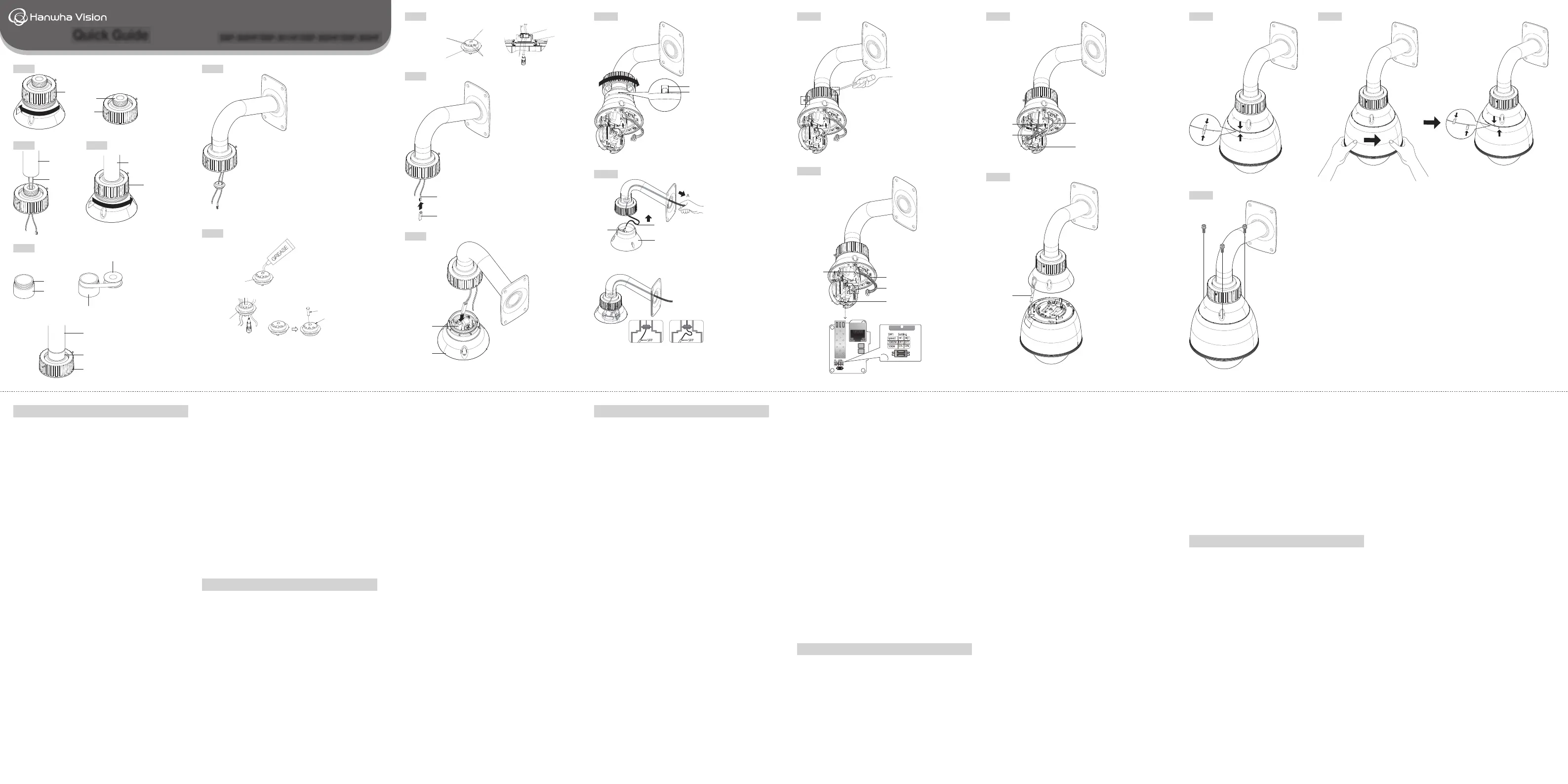
1. Zum Trennen des Deckels vom Verbindungsstück, den Deckel
in Pfeilrichtung drehen. (Abbildung 1)
2. Das freiliegende Kabel durch das Verbindungsstück zur
Außenseite der Befestigung oder des Mastens führen.
(Abbildung 2)
3.
Zum Verbinden der beiden Materialien das Verbindungsstück in
Pfeilrichtung drehen. (Abbildung 3)
Ist das Verbindungsstück an einer NPT TAP-Befestigung fest
gemacht, wie etwa im Produkt von PELCO, das Teflonband um
die
Zubehörverbindung wickeln, die Verbindung befestigen und
danach das Verbindungsstück befestigen. (Abbildung 4)
M
Wird das Produkt in einem Bereich installiert, in dem Feuchtigkeit
von außen durch die Befestigung oder den Masten dringen kann, die
Zubehörbuchse verwenden, um das Eindringen der Feuchtigkeit von
außen zu verhindern. (Abbildung 5)
-Schmieren Sie die Buchse mit Schmierfett ein und verbinden
Sie das Kabel mit dem richtigen Loch in der Buc
hse. In die
verbleibenden Löcher die Pins einstecken. (Abbildung 6)
-Die Buchse oben im Gehäuse mit dem optischen Kabel
verbinden, siehe Abbildung dazu. Drücken Sie das Netzkabel
auf seiner ganzen Länge, damit die Buchse richtig an das
Gehäuse befestigt wird, wie im Querschnittsdiagramm angezeigt.
(Abbildung 7)
4. Das optische Kabel mit dem SFP-Modul verbinden.
(Abbildung 8)
5. Das SFP-Modul am SFP-Steckplatz im Hauptgehäuse
befestigen. (Abbildung 9)
6.
Die Rippen- und Verbindungsrillen des Hauptgehäuses
verbinden, Form zusammenpassen und durch Drehen des
Deckels in Pfeilrichtung zusammen befestigen. (Abbildung 10)
J
Beim Befestigen der beiden Materialien, das optische Kabel von
außen ziehen, damit es sich innen nicht biegt. (Abbildung 11)
7. Die Schrauben auf beiden Seiten des Deckels anziehen, damit
der Deckel nicht in gegenläufiger Richtung lose wird.
(Die Schrauben befinden sich nicht vollständig
im Innern, da
nur eine bestimmte Länge eingesetzt wird.) (Abbildung 12)
8.
(SBP-300HF)
Das Ethernetkabel mit dem I/F PCB verbinden.
Das externe Netzkabel und das Stromversorgungskabel des
Hauptgehäuses in die Netzklemmleiste einstecken und mit
dem I/F PCB wie in der Abbildung verbinden. (Abbildung 13)
9. (SBP-301HF/302HF/303HF) Wie im Schritt 8.
Siehe die Abbildung für das Layout der I/F PCB Strom- und
Steckverbindung. (Abbildung 14)
10.
Befestigen Sie I/F PCB am Hauptgehäuse und verbinden Sie
das Sicherheitskabel der Kamera mit dem Hauptgehäuse.
(Abbildung 15)
11.
Verbinden Sie den installierten Sockel und das Hauptgehäuse
der Kamera durch Abgleich der Referenzindikatoren der
Richtung. (Abbildung 16)
12. Drehen Sie die Kamera in die Pfeilrichtung, damit die
Referenzindikatoren oben und unten denen im Bild rechts
entsprechen. (Abbildung 17)
13. Befestigen Sie das Hauptgehäuse un
d verwenden Sie dafür
die 3 Sechskantschrauben. (Abbildung 18)
14.
Die Versorgung dieses Produkts ist nur durch eine
Stromversorgungseinheit, „Klasse 2“ oder „LPS“, Leistung:
24 Vac (50 oder 60 Hz), min. 3,1 A bestimmt. (Haupteinheit
inbegriffen)
•Geschwindigkeitseinstellung
Die Standardeinstellung ist 1 Gbps; Die Geschwindigkeit kann bei
100 Mbps eingestellt werden, falls der Schalter auf “ON” gestellt
ist. (Abbildung 13)
•Unterstützt keine Er
eignisse “Netzwerkverbindung
unterbrochen”
Dieses Produkt unterstützt nicht die Alarmfunktion “Netzwerkverbindung
unterbrochen”, wenn ein Lichtwellenleiter als Zubehör der Netzwerk PTZ-
Kamera verbunden oder getrennt wird.
Italiano
1. Girare il tappo nella direzione mostrata dalla freccia per
separare il coperchio dalla giuntura. (Figura 1)
2. Far passare il cavo scoperto all’esterno del supporto o della
staffa attraverso la giuntura. (Figura 2)
3. Far girare la giuntura nella direzione mostrata dalla freccia per
collegare i due componenti. (Figura 3)
Se il componente della giuntura è fissato a un supporto
NPT TAP, come ad esempio il prodotto PELCO, avvolgere
l’accessorio di aggancio in nastro di teflon, stringere il
manicotto di giunzione e successivamente stringere la
giuntura. (Figura 4)
M
Se il prodottoè installato in un'area nella quale l'umidità esterna
può penetrare attraverso il supporto o la staffa, usare la boccola in
dotazione per bloccare l'afflusso di umidità dall'esterno. (Figura 5)
-Cospargere la boccola con grasso e collegare il cavo al relativo foro
della boccola. Attaccare i rimanenti cavi con i perni. (Figura 6)
-Collegare la boccola al cavo ottico nella parte superiore,
all'interno della custodia, come mostrato nella figura. Premere
completamente il cavo di alimentazione di modo che la boccola
sia correttamente fissata alla custodia come mostrato nel
diagramma trasversale. (Figura 7)
4. Collegare il cavo ottico al modulo SFP. (Figura 8)
5.
Stringere il modulo SFP all’apertura nell’unità principale. (Figura 9)
6. Collegare la nervatura dell’unità principale con la scanalatura
congiunta, facendo combaciare la forma. Quindi, stringerle
insieme facendo girare il coperchio nella direzione mostrata
dalla freccia. (Figura 10)
J
Mentre si stringonoi due materiali, spingere il cavo ottico
dall'esterno in modo che non si pieghi all'interno. (Figura 11)
7. Girare le viti ad entrambi i lati del coperchio per evitare che
questo si allenti nella direzione opposta.
(Le viti non si trovano completament
e all’interno, in quanto è
inserita soltanto una lunghezza specifica.) (Figura 12)
8. (SBP-300HF) Collegare il cavo Ethernet al I/F PCB.
Collegare il cavo di alimentazione esterno e il cavo di
alimentazione dell’unità principale alla morsettiera e collegarli
al I/F PCB come mostrato nella figura. (Figura 13)
9. (SBP-301HF/302HF/303HF) Uguale al passaggio 8.
Fare riferimento alla figura per il layout dell’alimentazione I/F
PCB e la connessi
one del connettore. (Figura 14)
10. Stringere il I/F PCB all’unità principale e collegare il cavo di
sicurezza della telecamera all’unità principale. (Figura 15)
11. Collegare la base installata e il corpo principale della
telecamera facendo combaciare gli indicatori di direzione di
riferimento. (Figura 16)
12. Far girare la telecamera nella direzione mostrata dalla freccia
di modo che gli indicatori di riferimento nella parte superiore e
i
nferiore combacino con l’immagine a destra. (Figura 17)
13. Stringere l’unità principale e la telecamera usando le 3 viti
esagonali. (Figura 18)
14.
Questo prodotto è stato ideato per essere fornito con
un’unità di alimentazione segnata come “Classe 2” o “LPS”
e classificata 24 Vac(50 o 60 Hz), min. 3.1 A. (Inclusa unità
principale)
•Impostazioni velocità
L’impostazione predefinita è 1 Gbps; è possibile impostare la
velocità a 100 Mbps se l’interruttore si
trova su “ON” (Figura 13)
•Non supporta l’evento “Scollegamento dalla rete”
Questo dispositivo non supporta la funzione di allarme
“Scollegamento dalla rete” durante la connessione o
disconnessione a un cavo a fibra ottica come accessorio della
telecamera di rete PTZ.
Figure 1Figure 5
Figure 6
Figure 7
Figure 8
Figure 9
Figure 10Figure 12Figure 14
Figure 15
Figure 16
Figure 18
Figure 17
Figure 11
QuickGuide
SBP-300HF/SBP-301HF/SBP-302HF/SBP-303HF
Cap
Figure 4
MOUNT or POLE
Coupling
Joint
NPT TAP
Coupling
Coupling
Teflon tape
Figure 2Figure 3
MOUNT or
POLE
MOUNT or
POLE
Joint
Cable
Joint
Cap
BUSH
BUSH
PIN
BUSH
BUSH
BUSH
HOUSING
POWER CABLE
ETC CABLE
OPTICAL CABLE
Optical Cable
SFP Module
SFP Slot
Housing
Housing
Optical Cable
SFP
< Good >< Not Good >
Safety wire
ON
1 2
SW1
ON
1 2
SW1
Figure 13
Ethernet
Cable
I/F PCB
External Power Cable
Main Body Power Cable
Ethernet Cable
External Power Cable
I/F PCB
Main Body Power Cable
Joint Groove
Main Body Rib
PT01-004143E
PT01-004143C-SBP-300HF-QG-14Langs.indd 42018-10-04 오후 2:38:51
PT01-004143E
Produktspezifikationen
| Marke: | Hanwha Vision |
| Kategorie: | Nicht kategorisiert |
| Modell: | SBP-301HF |
Brauchst du Hilfe?
Wenn Sie Hilfe mit Hanwha Vision SBP-301HF benötigen, stellen Sie unten eine Frage und andere Benutzer werden Ihnen antworten
Bedienungsanleitung Nicht kategorisiert Hanwha Vision

2 März 2026
1 März 2026
28 Februar 2026
28 Februar 2026
24 Februar 2026
24 Februar 2026
23 Februar 2026
23 Februar 2026
22 Februar 2026
22 Februar 2026
Bedienungsanleitung Nicht kategorisiert
Neueste Bedienungsanleitung für -Kategorien-
3 April 2026
3 April 2026
3 April 2026
3 April 2026
3 April 2026
3 April 2026
3 April 2026
3 April 2026
3 April 2026
3 April 2026