HK Audio Vortis VR 11510 Bedienungsanleitung

HK Audio Nicht kategorisiert Vortis VR 11510

Lies die bedienungsanleitung für HK Audio Vortis VR 11510 (20 Seiten) kostenlos online; sie gehört zur Kategorie Nicht kategorisiert. Dieses Handbuch wurde von 3 Personen als hilfreich bewertet und erhielt im Schnitt 4.9 Sterne aus 2 Bewertungen. Hast du eine Frage zu HK Audio Vortis VR 11510 oder möchtest du andere Nutzer dieses Produkts befragen? Stelle eine Frage

Seite 1/20
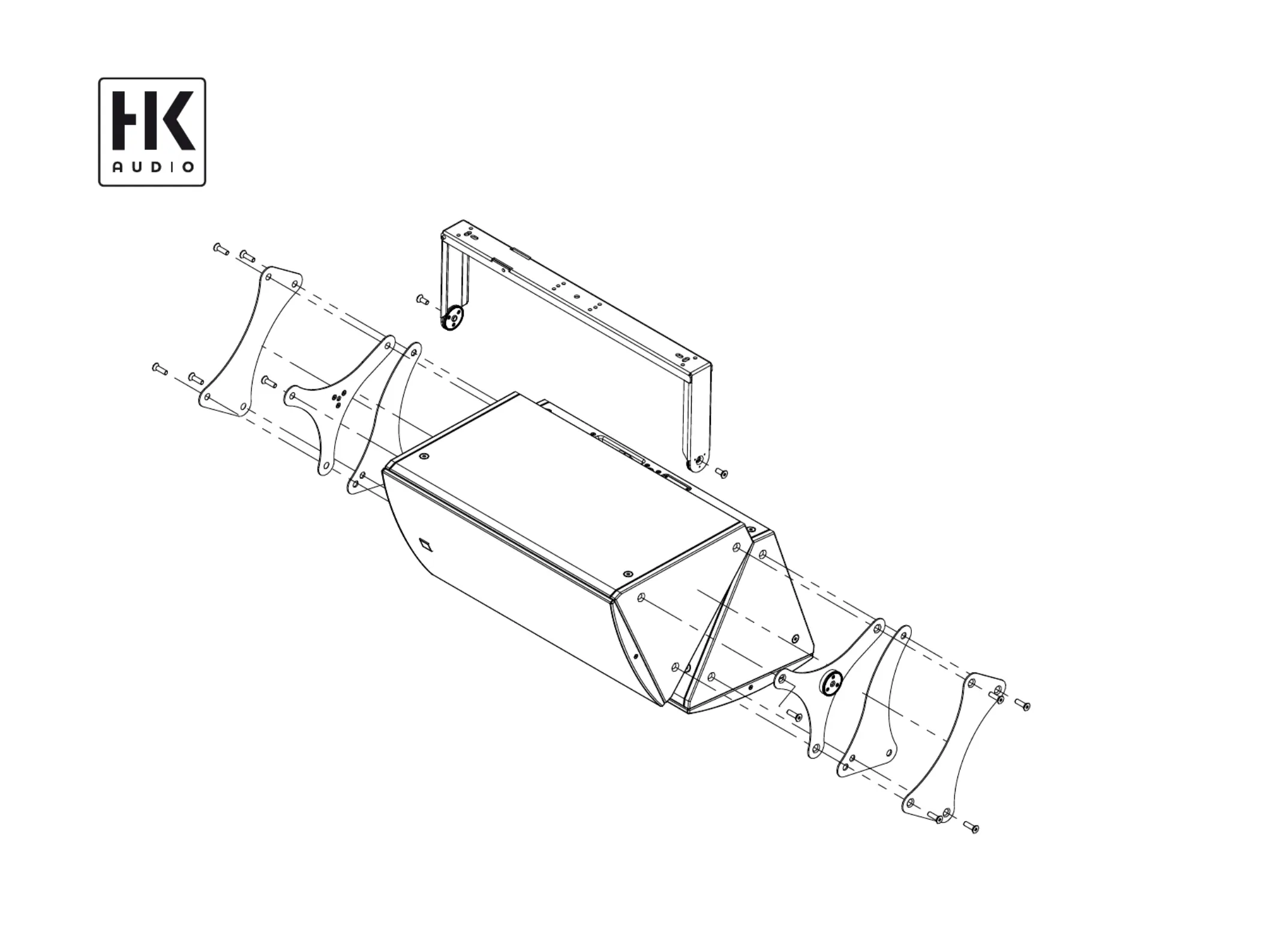
VORTIS / VORTIS 2 (EN 54)
• English
Mounting Accessories
• Manual 1.1
- 2 -
• English
Manual 1.1VORTIS / VORTIS 2 – Mounting Accessories
General Notes on Safety
for Loudspeaker Systems
manufacturer and only with the mounting accessories specified by the manufacturer in the
installation instructions. Read and heed the manufacturer’s installation instructions. The
indicated load-bearing capacity cannot be guaranteed and the manufacturer will not be
liable for damages in the event of improper installation or the use of unauthorized mounting
accessories.
The systems load-bearing capacity cannot be guaranteed and the manufacturer will not be
liable for damages in the event that loudspeakers, mounting accessories, and connecting and
attaching components are modified in any way.
Components affecting safety may only be repaired by the manufacturer or authorized agents,
otherwise the operating permit will be voided.
Installation may be performed by qualified personnel only, and then only at
pick-points with sufficient load-carrying capacity and in compliance with local building
regulations. Use only the mounting hardware specified by the manufacturer in the
installation instructions (screws, anchors, etc.). Take all the precautions necessary to ensure
bolted connections and other threaded locking devices will not loosen.
Fixed and portable installations (in this case, speakers and mounting accessories)
must be secured by two independent safeties to prevent them from falling. Safeties must be
able to catch accessories or parts that are loose or may become loose. Ensure compliance
with the given national regulations when using connecting, attaching, and rigging devices.
Factor potential dynamic forces (jerk) into the equation when determining the proper size
and load-bearing capacity of safeties.
Be sure to observe speaker stands’ maximum load-bearing capacity. Note that for
reasons of design and construction, most speaker stands are approved to bear centric loads
only; that is, the speakers mass has to be precisely centered and balanced. Ensure speaker
stands are set up stably and securely. Take appropriate added measures to secure speaker
stands, for example when:
- the floor or ground surface does not provide a stable, secure base.
- they are extended to heights that impede stability.
- high wind pressure may be expected.
- there is the risk that they may be knocked over by people.
Special measures may become necessary as precautions against unsafe audience behavior.
Do not set up speaker stands in evacuation routes and emergency exits. Ensure corridors are
wide enough and put proper barriers and markings in place when setting speaker stands up
in passageways. Mounting and dismounting are especially hazardous tasks. Use aids suitable
for this purpose. Observe the given national regulations when doing so.
Wear proper protection (in particular, a helmet, gloves, and safety
shoes) and use only suitable means of ascent (ladders, scaffolds, etc.) during installation.
Compliance with this requirement is the sole responsibility of the company performing the
installation.
WARNING! After installation, inspect the system comprised of the mounting fixtures
and loudspeakers to ensure it is properly secured.
The operator of loudspeaker systems (fixed or portable) must regularly inspect or task a
third party to regularly inspect all system components in accordance with the given countrys
regulations and have possible defects repaired immediately.
We also strongly recommend maintaining a logbook or the like to document all inspections.
Also be sure to provide sufficient safety margins for the rigging points used for flown
systems. Observe the given national regulations when doing so.
Professional loudspeaker systems can produce harmful volume levels. Even prolonged
exposure to seemingly harmless levels (starting at about 95 dBA SPL) can cause permanent
hearing damage! Therefore we recommend that everyone who is exposed to high volume
levels produced by loudspeaker systems wears professional hearing protection (earplugs or
earmuffs).
Manufacturer: Stamer Musikanlagen GmbH, Magdeburger Str. 8, 66606 St. Wendel, Germany
Version 2.8 08/2019
Table of Contents
1 Individual Components .......................................... 3
2 Installation Options ............................................... 5
3 General Installation Instructions ...........................8
4 Clustering VORTIS (2) Enclosures .........................13
5 Dimensional Drawings of Component Parts ........16
6 Aligning Horns ......................................................19
7 Ball Impact Safety ................................................19
- 3 -
• English
Manual 1.1VORTIS / VORTIS 2 – Mounting Accessories
1 Individual Components
Note: The accessories for VR(2)-11210, VR(2)-11510,
VR(2)-11214, VR(2)-11514, and VR(2)-21214 models are
identical except for the U-bracket.The VR(2)-10810’s
hardware has the same properties, but the design of
some components is di erent.
1.1 AP-10 B
This attachment point has a workload limit (WLL) of 360 kg/
794 lbs, and helps in the attaching and securing of VORTIS (2)
enclosures with M10 rigging points to steel cables or chains. A bolt
with R-clip allows for quick installation.
1.2 U-bracket including Mounting Plates
This U-bracket serves to mount VORTIS (2) speakers to walls
and ceilings. You can aim and align cabinets using a combination
of speaker tilt and/or wall plate. The U-bracket comes with two
mounting plates included with delivery that attach it to the
enclosure. For each model of loudspeaker a di erent U-bracket is
available.
1.3 Speaker Tilt with Angular Alignment
This adapter adjusts the tilt angle of VORTIS (2) cabinets in
5° steps up to a maximum of 45°. The U-bracket connects the
enclosure and speaker tilt.
1.4 Wall Plate
This plate o ers the possibility to mount the speakers to walls.
It lets you rotate the enclosure in 5° steps. You need either the
U-bracket in combination with the speaker tilt or just the VORTIS
(2) cabinet’s U-bracket to attach the cabinet to the wall plate.
1.5 Cluster Plates
Speaker cabinets may be clustered to change their directivity. This
cluster plate lets you array cabinets vertically and horizontally. You
will need the extension plate to cluster more than two enclosures.
Note: The VR(2)-10810 requires a di erent cluster plate!
The 0° plate is suitable for the 40° x 60° horn, and the 10° plate for
60° x 40° and 55° x 90° horns.
0° VORTIS (2) cluster plate
10° VORTIS (2) cluster plate


Produktspezifikationen

Marke: HK Audio
Kategorie: Nicht kategorisiert
Modell: Vortis VR 11510

Brauchst du Hilfe?

Wenn Sie Hilfe mit HK Audio Vortis VR 11510 benötigen, stellen Sie unten eine Frage und andere Benutzer werden Ihnen antworten