Hoffman G52 Bedienungsanleitung
Lies die bedienungsanleitung für Hoffman G52 (40 Seiten) kostenlos online; sie gehört zur Kategorie Heizung. Dieses Handbuch wurde von 33 Personen als hilfreich bewertet und erhielt im Schnitt 4.7 Sterne aus 3 Bewertungen. Hast du eine Frage zu Hoffman G52 oder möchtest du andere Nutzer dieses Produkts befragen? Stelle eine Frage
Seite 1/40
© 2017 Pentair Equipment Protection89116684
Rev. C
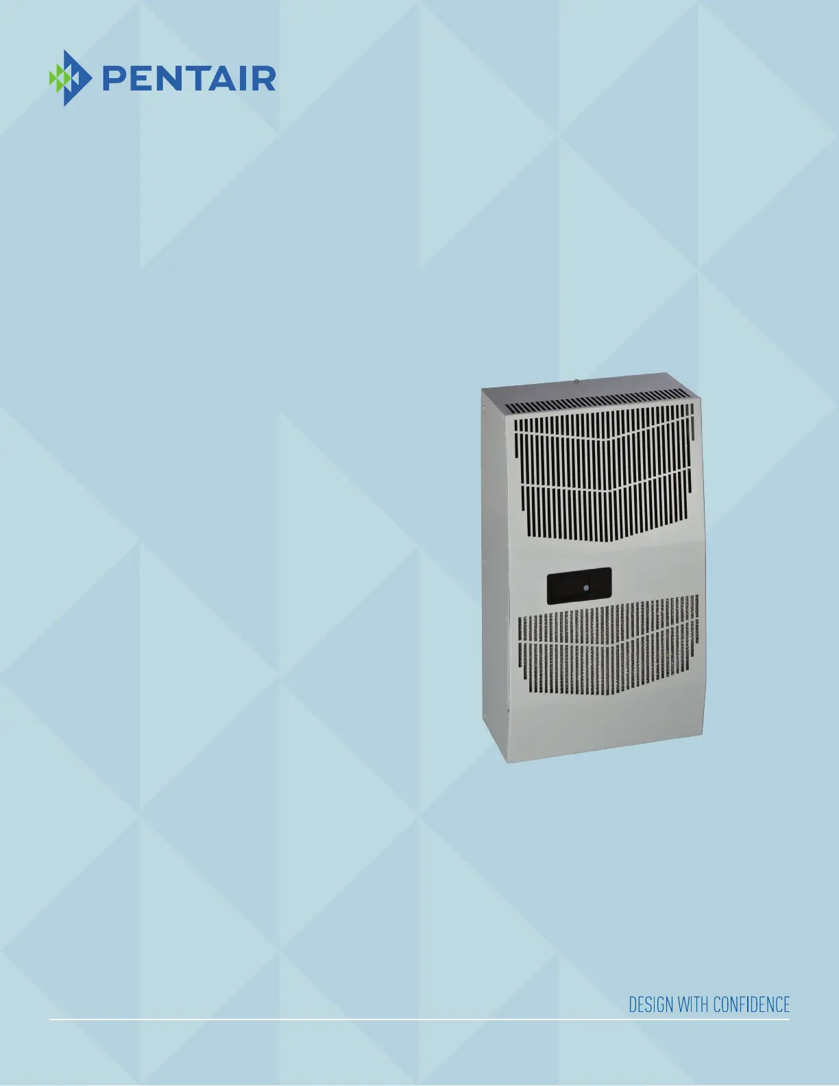
P/N 89116684
SPECTRACOOL
Air Conditioner
G28 Model
INSTRUCTION MANUAL
Produktspezifikationen
| Marke: | Hoffman |
| Kategorie: | Heizung |
| Modell: | G52 |
| Breite: | 434.8 mm |
| Tiefe: | 296 mm |
| Gewicht: | 58059 g |
| Produktfarbe: | Grau |
| Internationale Schutzart (IP-Code): | IP56 |
| Steuerung: | Tasten |
| Höhe: | 1338 mm |
| AC Eingangsspannung: | 200-250 V |
| Typ: | Elektrischer Raumheizlüfter |
| Betriebsanleitung: | Ja |
| Gehäusematerial: | Kunststoff |
| Temperatur (max): | 55 °C |
| Ein-/Ausschalter: | Ja |
| Regelbare Temperatur: | Ja |
| Temperatur (min): | -8 °C |
| Heizleistung: | 3500 W |
| Geeignet für: | Drinnen |
| Platzierungsoptionen: | Flur |
| Hitzeleistung (min): | - W |
| Tragbar: | Ja |
| Maximale Kapazität: | 8000 BTU/h |
Brauchst du Hilfe?
Wenn Sie Hilfe mit Hoffman G52 benötigen, stellen Sie unten eine Frage und andere Benutzer werden Ihnen antworten
Bedienungsanleitung Heizung Hoffman

21 Juli 2025
21 Juli 2025
Bedienungsanleitung Heizung
Neueste Bedienungsanleitung für -Kategorien-
3 April 2026
3 April 2026
3 April 2026
2 April 2026
2 April 2026
1 April 2026
31 März 2026
31 März 2026
31 März 2026
31 März 2026