Intermatic Arista ALC1-R Bedienungsanleitung
Intermatic Nicht kategorisiert Arista ALC1-R
Lies die bedienungsanleitung für Intermatic Arista ALC1-R (4 Seiten) kostenlos online; sie gehört zur Kategorie Nicht kategorisiert. Dieses Handbuch wurde von 12 Personen als hilfreich bewertet und erhielt im Schnitt 4.6 Sterne aus 4 Bewertungen. Hast du eine Frage zu Intermatic Arista ALC1-R oder möchtest du andere Nutzer dieses Produkts befragen? Stelle eine Frage
Seite 1/4
COMPLIANCE
This device complies with part 15 of the FCC. Operation is subject to
the following two conditions: (1) this device may not cause harmful
interference, and (2) this device must accept any interference received,
including interference that may cause undesired operation.
FCC NOTE:The manufacturer is not responsible for any radio or TV
interference caused by unauthorized modifications to this equipment.
Such modifications could void the user’s authority to operate the
equipment.
NOTE:This equipment has been tested and found to comply with the
limits for a Class B digital device, pursuant to Part 15 of the FCC Rules.
These limits are designed to provide reasonable protection against
harmful interference in a residential installation. This equipment
generates, uses and can radiate radio frequency energy and, if not
installed and used in accordance with the instructions may cause
harmful interference to radio communications. However, there is no
guarantee that interference will not occur in a particular installation. If
this equipment does cause harmful interference to radio or television
reception, which can be determined by turning the equipment off and
on, the user is encouraged to try to correct the interference by one or
more of the following measures:
• Reorient or relocate the receiving antenna.
• Increase the separation between the equipment and receiver.
• Connect the equipment into an outlet on a circuit different from that
to which the receiver is connected.
• Consult the dealer or an experienced radio/TV technician for help.
Important note:To comply with the FCC RF exposure compliance
requirements, no change to the antenna or the device is permitted.
Any change to the antenna or the device could result in the device
exceeding the RF exposure requirements and void user ’s authority to
operate the device.
This Class B digital apparatus complies with ICES-005 of Canada.
WARNINGS/SAFETY
WARNING
Risk of Fire or Electric Shock
• Disconnect power at the circuit breaker(s) or disconnect
switch(es) before installing or servicing.
• Installation and/or wiring must be in accordance with national
and local electrical code requirements.
• Only use copper conductors rated 105°C minimum
• Battery is not user replaceable.
• Do NOT use timer to control devices that could have dangerous
consequences due to inaccurate timing, such assun lamps,
saunas, heaters, and crock pots.
• Class 2 connections shall be torqued to 4.5 lb-in.
NOTICE
Dispose of product per local regulations on the disposal of lithium
batteries.
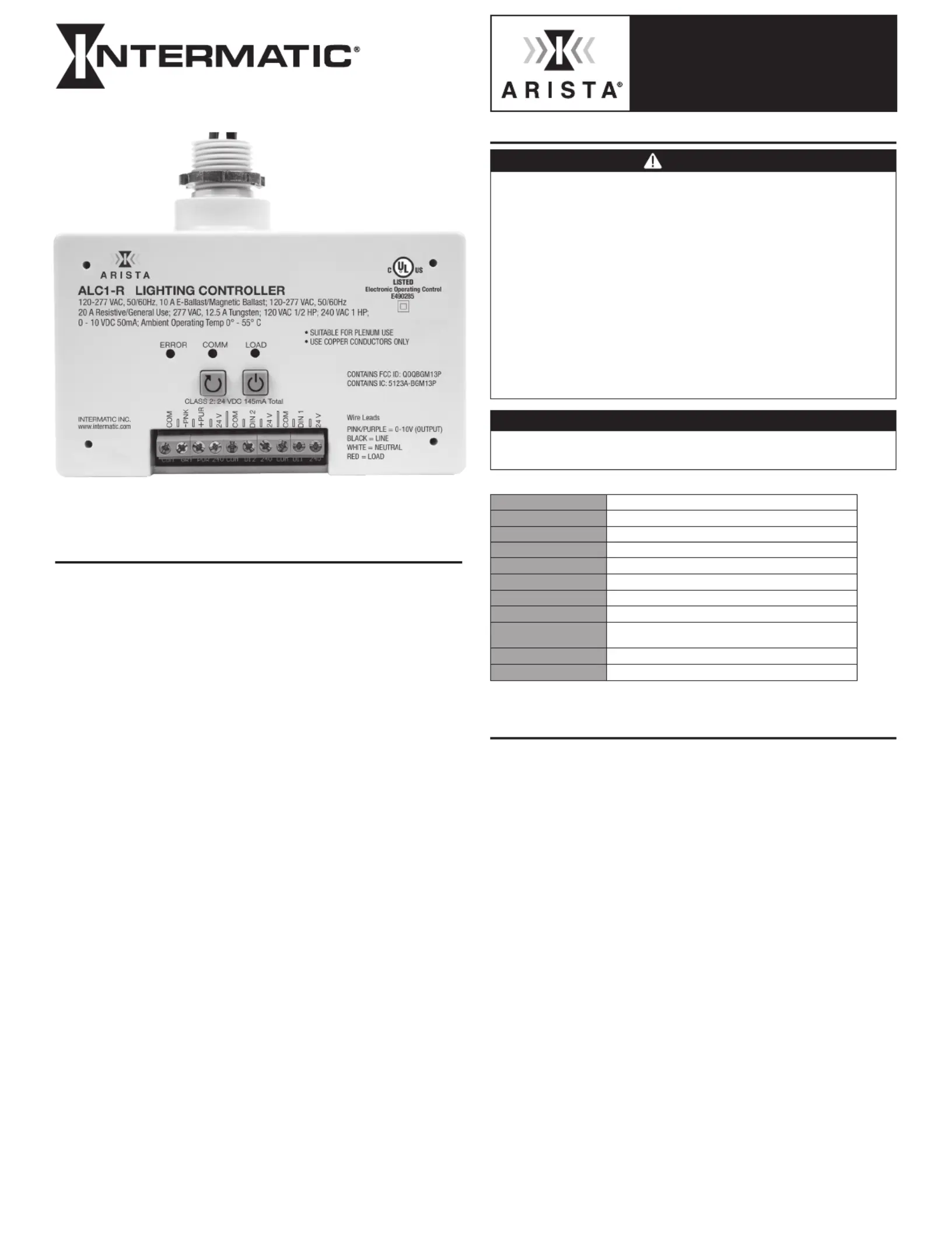
Ratings
1
Operating Voltage120-277 VAC, 50/60 Hz
Magnetic Ballast10 A, 120-277 VAC, 50/60 Hz
Electronic Ballast/LED10 A, 120-277 VAC, 50/60 Hz
Resistive20 A, 120-277 VAC
General Use20 A, 120-277 VAC
Tungsten12.5 A, 277 VAC
Motor120 VAC, 1/2 HP; 240 VAC, 1 HP
Class 10-10 VDC output = 50 mA
Class 2
DIN Voltage = 24 VDC (-10%, + 15%)
max mA = 145 mA Total
Operating Temperature0° to 55° C (32° to 131° F)
Dimensions5" H x 3.10" W x 1.86" D
1
The ALC1-R is suitable for plenum use.
1
Type 1 action, operating control, PD2 pollution degree, Impulse voltage 4000V.
INSTALLATION
1. Turn off power to the controlling circuit.
2. Determine the electrical junction box that will be used for
mounting. (Standard or Deep 4” junction box is recommended).
3. Determine the proper ½” knockout to be used.
4. Remove the knockout from the electrical box.
5. Insert nipple with wire leads through the knockout opening.
6. Use provided locknut to secure the ALC1-R to the electrical box.
7. Tighten locknut accordingly to make sure ALC1-R is secured.
8. Connect wiring following the wiring diagrams provided below.
9. Turn power ON to the controlling circuit.
10. Verify the Green LED indicator activates and deactivates upon
press of the Power button.
NOTES:ALC1-R may be programmed to control 0-10VDC dimming
fixtures or control a receptacle load. For Programming instructions
please visit www.Intermatic.com. The Arista App is available on Apple
App and Google Play stores. (Search for Arista by Intermatic)
Bluetooth Operations have a maximum range of 100’
This device communicates with other devices and should not be
installed in a metal enclosure.
ALC1-R
0-10 V Lighting Controller
Produktspezifikationen
| Marke: | Intermatic |
| Kategorie: | Nicht kategorisiert |
| Modell: | Arista ALC1-R |
Brauchst du Hilfe?
Wenn Sie Hilfe mit Intermatic Arista ALC1-R benötigen, stellen Sie unten eine Frage und andere Benutzer werden Ihnen antworten
Bedienungsanleitung Nicht kategorisiert Intermatic

5 November 2025
5 November 2025
4 September 2025
3 September 2025
20 August 2025
20 August 2025
4 August 2025
2 August 2025
2 August 2025
2 August 2025
Bedienungsanleitung Nicht kategorisiert
Neueste Bedienungsanleitung für -Kategorien-
3 April 2026
3 April 2026
3 April 2026
3 April 2026
3 April 2026
3 April 2026
3 April 2026
3 April 2026
3 April 2026
3 April 2026