Intermatic E1010 Bedienungsanleitung
Lies die bedienungsanleitung für Intermatic E1010 (1 Seiten) kostenlos online; sie gehört zur Kategorie Nicht kategorisiert. Dieses Handbuch wurde von 11 Personen als hilfreich bewertet und erhielt im Schnitt 4.2 Sterne aus 4 Bewertungen. Hast du eine Frage zu Intermatic E1010 oder möchtest du andere Nutzer dieses Produkts befragen? Stelle eine Frage
Seite 1/1
How to install and
operate your NEW
2
4
automatic
in-wall
timer
model:E-1010
For Automatic Operation:
1. Depress and slide ON and OFF trippers to desired timings.
2. Rotate Dial (Clockwise only) until exact time of day is aligned with
Time indicator line.
To Discontinue Automatic Operation:
Gently pull center dial knob out (until click is heard).
If Timer is in the “ON” position, light or appliance will stay on.
If Timer is in the “OFF” position, light or appliance will stay off.
To return to automatic operation push center dial knob back into
original position.
For Manual Operation
Use manual control on front of panel as indicated. This will NOT effect next
automatic operation.
I
NTERMATIC INCORPORATED
SPRING GROVE, ILLINOIS 60081-9698
158EB12391
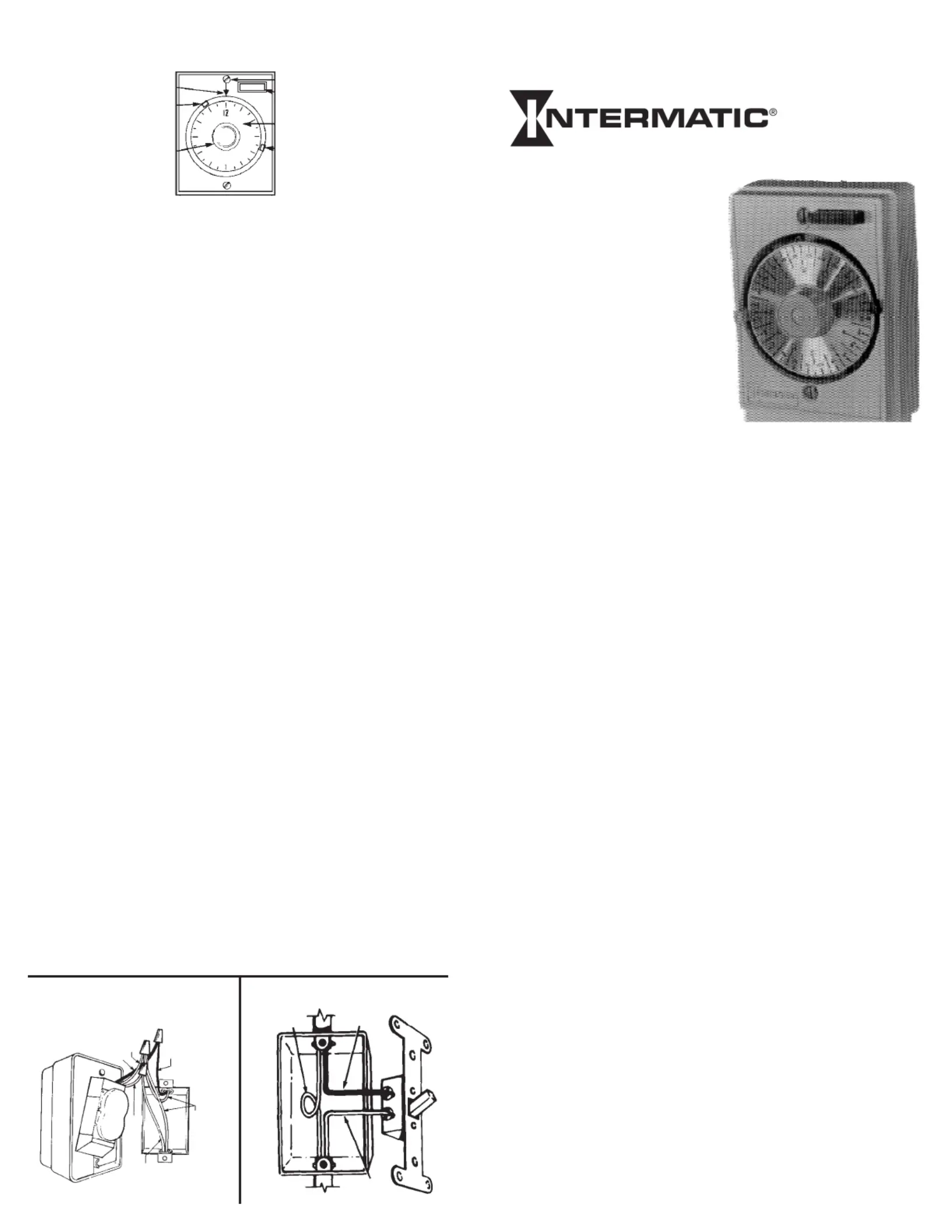
HOW TO OPERATE YOUR TIMER. . . .
TIME INDICATOR LINE
“ON” TRIPPER
CENTER DIAL KNOB
MANUAL CONTROL
24-HOUR DIAL
THIS IN-WALL TIMER. . . .
. . .is designed to be easily installed in an electrical junction box to
replace a wall switch. Functioning as an “automatic” wall switch,
it will follow a preset program and will repeat it every 24 hours.
Nevertheless, the program can be easily changed, manually
interrupted or suspended at any time.
HOW TO INSTALL. . .
1. Disconnect your electrical power for safety during installation.
2. Remove wall plate and disconnect light switch. Make sure both
“hot” and neutral wires are present in the junction box.(See
Fig. 1.). If both wires are not present, additional wiring will be neces-
sary before installation can be completed.
3. Connect red timer wire to wire from fixture using wire connector.
Connect black timer wire to the (usually black or red) wire in “hot”
junction box using wire connector. Cut white wire in junction box (or
open splice) and strip 1/2” of insulation on both wires. Connect white
timer wire to white wires in junction box using wire connector. (See
Fig. 2)
4. If the wall switch you are replacing had separate grounding con-
ductors connected to the screw on the switch, make sure GREEN
these wires are now securely connected to the wall box, METAL
or, if your box is non-metallic (plastic) the wires are securely tied
together.
5. Check that all wire connections are secure.
6. Place all wires inside junction box. Fit timer over junction box
first, making sure that all wires and twist on wire connectors clear
the back of timer motor. DO NOT FORCE. Next, install timer using
(2) mounting screws furnished.
7. Reconnect your electrical power. Set timer - see operating
instructions.
FIGURE 1
FIGURE 2
Wire From
Fixture
“HOT”
(Black or Red)
Uncut
white
wire
(or splice)
WIRE
FROM
FIXTURE
WHITE
BLACK
BLACK
WHITE
ONE YEAR LIMITED WARRANTY
If within the warranty period specified, this product fails due to a defect in material or
workmanship, Intermatic Incorporated will repair or replace, at its sole option, the unit
free of charge. this warranty applies only to the original purchaser and is not transfer-
able. This warranty does not apply to: (a) damage caused by accident, abuse, mishan-
dling, dropping, acts of God, or any negligent use; (b) units which have been subject
to unauthorized repair, opened, taken apart or otherwise modified; (c) units not used
in accordance with instructions; (d) damages exceeding the cost of the product. Some
states do not allow a limitation of damages, so the foregoing limitation may not apply
to you. This warranty gives you specific legal rights and you may have other rights that
vary from state to state.
INTERMATIC INCORPORATED WILL NOT BE LIABLE FOR INCIDENTAL OR
CONSEQUENTIAL DAMAGES. THIS WARRANTY IS IN LIEU OF ALL OTHER
EXPRESS OR IMPLIED WARRANTIES. ALL IMPLIED WARRANTIES, INCLUDING
THE WARRANTY OF MERCHANTABILITY AND THE WARRANTY OF FITNESS
FOR A PARTICULAR PURPOSE, ARE HEREBY MODIFIED TO EXIST ONLY
AS CONTAINED IN THIS LIMITED WARRANTY, AND SHALL BE OF THE SAME
DURATION AS THE WARRANTY PERIOD STATED ABOVE.
This warranty service is available by either (a) returning the product to the dealer from
whom the unit was purchased, or (b) mailing postage prepaid to the nearest authorized
service center listed. Please be sure to wrap the product securely when mailing to avoid
shipping damage. This warranty is made by: Intermatic Incorporated/After Sales Service/7777
Winn Rd., Spring Grove, IL 60081-9698/815-675-7000 http://www.intermatic.com
All wiring and installation must conform to national and / or local electrical codes.
HOUR
FOR SINGLE POLE WALL SWITCH
APPLICATION/REPLACEMENT ONLY
RATED: 15 AMP. MAXIMUM. 12 AMP.
(1500 WATT) TUNGSTEN, 12 FULL LOAD
AMPERES - 125 VOLTS, 60 HZ.
“OFF” TRIPPER
MOUNTING SCREWS (2)
Produktspezifikationen
| Marke: | Intermatic |
| Kategorie: | Nicht kategorisiert |
| Modell: | E1010 |
Brauchst du Hilfe?
Wenn Sie Hilfe mit Intermatic E1010 benötigen, stellen Sie unten eine Frage und andere Benutzer werden Ihnen antworten
Bedienungsanleitung Nicht kategorisiert Intermatic

5 November 2025
5 November 2025
4 September 2025
3 September 2025
20 August 2025
20 August 2025
4 August 2025
2 August 2025
2 August 2025
2 August 2025
Bedienungsanleitung Nicht kategorisiert
Neueste Bedienungsanleitung für -Kategorien-
3 April 2026
3 April 2026
3 April 2026
3 April 2026
3 April 2026
3 April 2026
3 April 2026
3 April 2026
3 April 2026
3 April 2026